
Vehicle mirror with organic light-emitting display

a technology of organic light and vehicle mirrors, applied in the field of mirrors, can solve the problems of restricting the possible use of vehicle mirror illumination, and achieve the effect of reducing equipment diversity and simple mounting

Inactive Publication Date: 2009-05-07
OLYMPUS HLDG +1
View PDF9 Cites 12 Cited by
  • Summary
  • Abstract
  • Description
  • Claims
  • Application Information

AI Technical Summary

Benefits of technology

[0010]According to the invention, the illumination unit according to the invention has an OLED (Organic Light Emitting Diode). OLEDs constitute an electronic component which generally has a plurality of thin organic current-conducting layers. The OLEDs may be constructed so as to have a thickness of less than 3 mm, preferably less than 1.4 mm and particularly preferably <1 mm. Preferably, but by no means necessarily, the OLEDs have a transmission of >70%, and particularly preferably >75% in the non-driven state. OLEDs generally have a carrier layer, for example, glass, to which a luminous coating is applied, and a covering layer, for example, likewise glass. The carrier layer preferably has a reflective layer, which reflects the light emitted by the diodes and which acts as a mirror in the non-driven state of the diodes. The OLEDs emit a bright, diffuse light that does not dazzle. OLEDs are distinguished by a very fast response speed. By attachment of an appropriate filter, a white light-emitting OLED can be modified to emit light in any desired color. This is advantageous, for example for reading light. However, a color effect of the OLEDs can also be obtained without filters. Furthermore, OLEDs are very lightweight and have an extremely high durability, such that, by way of example, the weight of a vehicle and the replacement intervals of the illumination unit can be reduced. In general, replacement can be completely obviated on account of the long lifetime. Comparatively large-area illuminations can also be realized due to the comparatively low weight of the OLEDs.
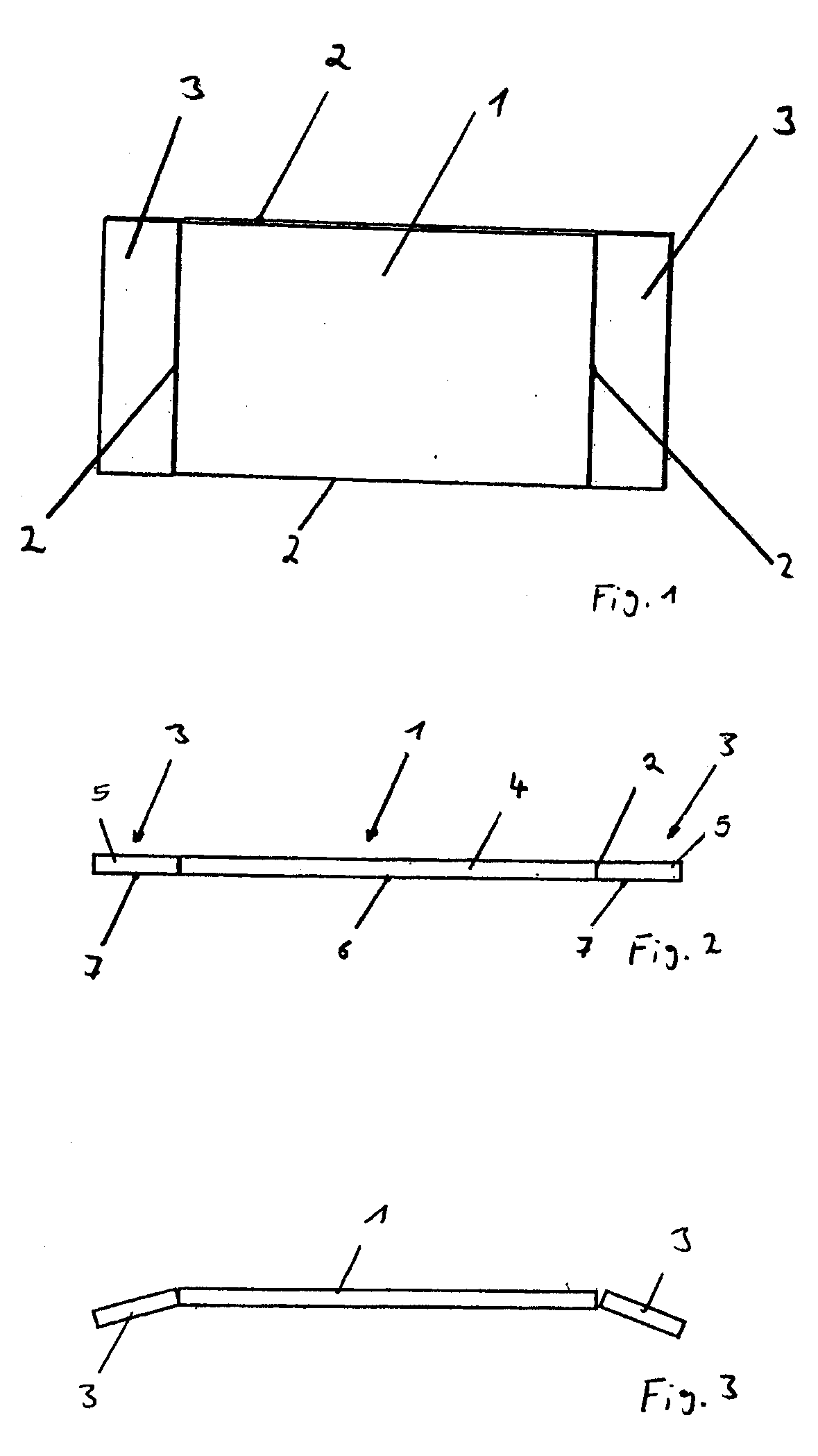
[0013]In another exemplary embodiment, the OLED is arranged in curved fashion. In yet another variation, the OLED is arranged in a manner angled with respect to the mirror. This latter embodiment has the advantage, in particular that light emitted by the OLED does not dazzle the observer, and that the OLED in the turned-off state enables three-dimensional observation for the observer.

Problems solved by technology

These disadvantages restrict the possible uses of such illuminations as vehicle mirror illumination, in particular as make-up mirror illumination.

Method used


Image

  • Vehicle mirror with organic light-emitting display
  • Vehicle mirror with organic light-emitting display

Examples


Embodiment Construction

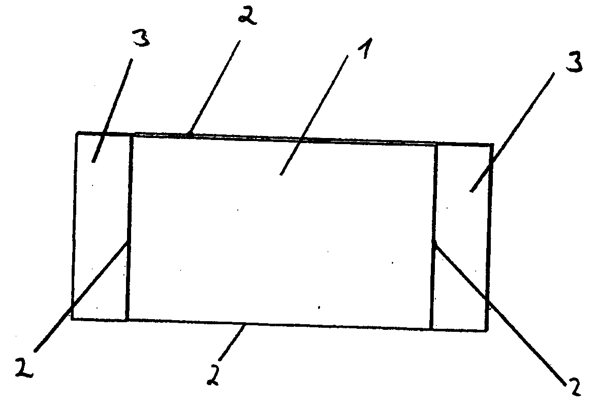
[0021]FIG. 1 illustrates a mirror 1 according to one embodiment of the invention. In the present case, the mirror 1 is configured in rectangular fashion and has a respective OLED 3 at the right-hand and the left-hand surface of the periphery 2 of said mirror. The OLED is a reflective OLED, which acts like a mirror in the non-driven (i.e., non-energized) state, such that the surfaces 1 and 3 in the non-driven state of the OLEDs act like a large, essentially homogeneous mirror surface. In the driven state, the reflective OLEDs 3 function as luminaires and, in the case of a vanity mirror, illuminate for example the observer's face.

[0022]FIG. 2 illustrates a side view of the mirror in accordance with FIG. 1. This view reveals that the mirror 1 comprises a substrate 4, a glass substrate in the present case, which has a reflective surface 6 at its rear side. The OLEDs 3 are identified by the reference symbol 5 and have a reflective surface 7 at their rear side. The OLED 3 comprises a cove...


PUM


Abstract

The invention relates to a mirror in a motor vehicle, in particular a make-up lighted or / vanity style mirror. At least one preferably reflective organic light-emitting diode display abuts the periphery of said mirror.

Description

CROSS REFERENCE TO RELATED APPLICATIONS[0001]None.BACKGROUND OF THE INVENTION[0002]1. Field of the Invention[0003]The present invention relates to a mirror in a motor vehicle, in particular a vanity mirror, at the periphery of which is arranged at least one preferably reflective OLED without a spacing.[0004]2. Related Art[0005]Mirrors are sufficiently known from the prior art and are nowadays equipped with additional features. By way of example, DE 101 40 689 A1 discloses a vehicle mirror comprising a mirror plate and an organic light-emitting diode display (OLED) formed from two substrates and an OLED layer, the mirror plate directly forming one of the substrates of the OLED display. In the case of said mirror it is possible to project information into the reflective surface. A further rear-view mirror with a display unit is disclosed in DE 103 25 845 A1. Furthermore, it is known from the prior art for mirrors to have illuminations. The illumination of said mirrors is based, in acc...

Claims


Application Information

Patent Timeline
Patent Type & Authority Applications(United States)
IPC IPC(8): B60Q3/02
CPCB60J3/0282B60R1/1207B60Q3/023B60Q3/0226B60Q3/252B60Q3/258B60R1/12B60J3/02H10K59/00B60Q3/20
Inventor MULLER, WOLFGANGHILBERT, BERNARD
Owner OLYMPUS HLDG
Learn More