Sensor-Equipped Wheel Support Bearing Assembly

a technology of bearings and bearings, which is applied in the direction of force sensors, instruments, transportation and packaging, etc., can solve the problems of deformation and strain on the sensor mounting members, and achieve the effects of reducing the cost of mass production, less sensitivity, and good sensitivity

Inactive Publication Date: 2009-05-14
NTN CORP
View PDF20 Cites 20 Cited by
  • Summary
  • Abstract
  • Description
  • Claims
  • Application Information

AI Technical Summary

Benefits of technology

[0013]An object of the present invention is to provide a sensor-incorporated wheel support bearing assembly, in which the cost during the mass production can be reduced and in which, by compactly installing a load sensor and any of a rotation sensor, a temperature sensor and a status detecting sensor for detecting a status of the wheel support bearing assembly in the vehicle, (i) a load acting on a wheel of the automotive vehicle and a rotation thereof can be detected, (ii) a load acting on a wheel of the automotive vehicle can be certainly detected with less sensitivity to temperature changes and thus with good sensitivity and defects occurring in the wheel support bearing assembly also can be detected, or (iii) a load acting on a wheel of the automotive vehicle can be detected with good sensitivity.

Problems solved by technology

According to the first construction of the sensor-incorporated wheel support bearing assembly, when during the travel of the automotive vehicle a load acts on the rotating member, the stationary member is deformed through the rolling elements, and the deformation brings about a strain on the sensor mounting member.

Method used


Image

  • Sensor-Equipped Wheel Support Bearing Assembly
  • Sensor-Equipped Wheel Support Bearing Assembly
  • Sensor-Equipped Wheel Support Bearing Assembly

Examples


second embodiment

[0103]FIG. 9 to FIG. 11 show the present invention. This embodiment differs from the first embodiment in the structure of the ring member 22 constituting the sensor unit 21, but other structural features of the second embodiment are similar to those of the first embodiment, and thus same reference numerals are denoted for the common parts and the description thereof will be omitted.

[0104]The ring member 22 has, as represented by a sectional shape shown in FIG. 11, a contact ring portion (a first contact ring portion) 22a in contact with the inner peripheral surface of the outer member 1, a non-contact ring portion (a first non-contact ring portion) 22b not in contact with the inner peripheral surface of the outer member 1 and extending axially of the ring member 22, and a thick-walled portion (a second non-contact ring portion) 22c having a wall thickness greater than those of the first non-contact ring portion 22b and the first contact ring portion 22a, and positioned adjacent to t...

third embodiment

[0109]FIG. 12 to FIG. 14 show the present invention. This embodiment differs from the first and the second embodiments in the structure of the ring member 22 constituting the sensor unit 21, but other structural features of the third embodiment are similar to those of the first and the second embodiments, and thus same reference numerals are denoted for the common parts and the description thereof will be omitted.

[0110]As shown in FIG. 14, the second embodiment is similar to the second embodiment in that the ring member22 has the contact ring portion (the first contact ring portion) 22a in contact with the inner peripheral surface of the outer member 1 and the non-contact ring portion (the first non-contact ring portion) 22b not in contact with the inner peripheral surface of the outer member 1 and extending axially of the ring member 22, but is different from the second embodiment in that the ring member 22 further has a flange portion (a second non-contact ring portion) 22d protru...

sixth embodiment

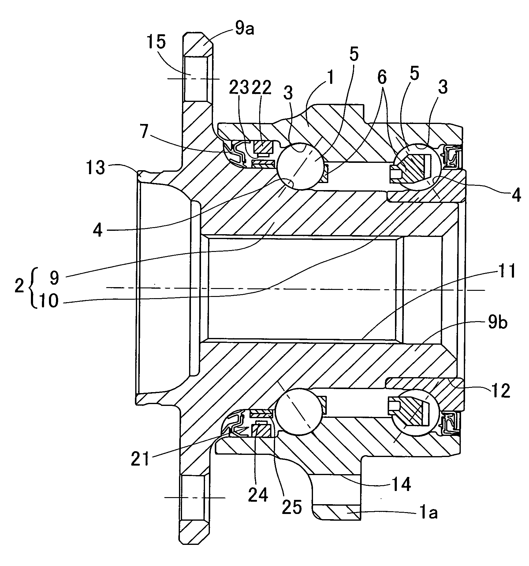
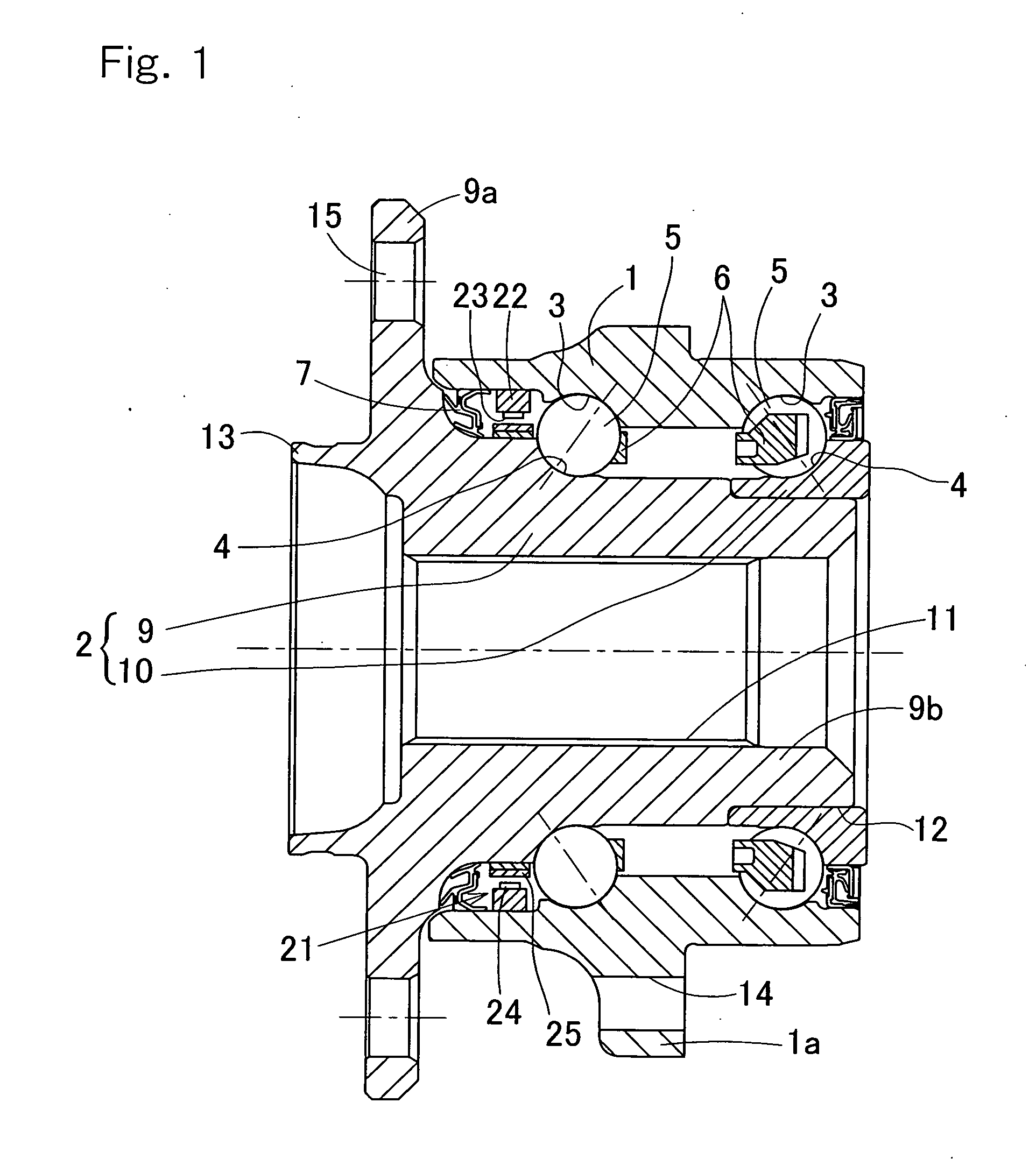
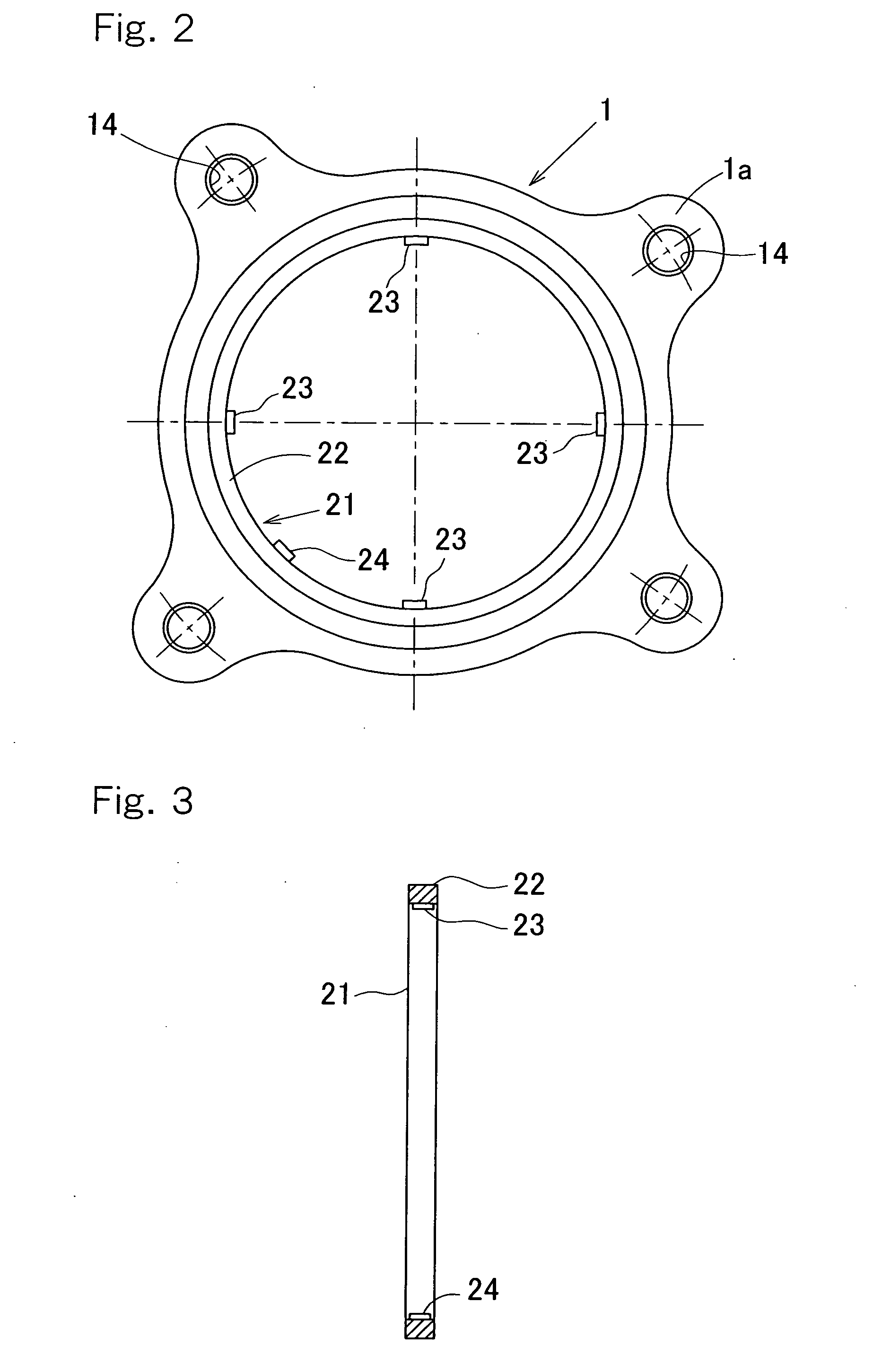
[0127]FIG. 21 to FIG. 23 show the present invention. This embodiment differs from the first to the fifth embodiments in the structure of the sensor unit 21. The sensor unit 21 has the sensor mounting member 22 fitted to the surface of the outer member 1 at a portion in a circumferential direction thereof, the strain sensor 23 for measuring a strain on the sensor mounting member 22, which is affixed to the sensor mounting member 22, and the magnetic sensor 24 for detecting a rotation, which is of a type different from the strain sensor 23 and also affixed to the sensor mounting member 22. Other structural features of this embodiment are similar to those of the first to the fifth embodiments, and thus same reference numerals are denoted for the common parts and the description thereof will be omitted.

[0128]As shown in FIG. 23A, the sensor mounting member 22 has a substantially elongated arcuate shape corresponding to the shape of the inner peripheral surface of the outer member 1 and ...


PUM


Abstract

A sensor-equipped wheel support bearing assembly, enabling the cost during the mass production to be reduced, includes an outer member (1), an inner member (2), a plurality of rolling elements (3) interposed between the opposed raceway surfaces. One of the outer member (1) and the inner member (2), which serves as a stationary member, is fitted with a sensor mounting member (22) provided with a strain sensor (23). The sensor mounting member (22) is further provided with a status detecting sensor (24) for detecting different status other than a strain.

Description

BACKGROUND OF THE INVENTION[0001]1. (Field of the Invention)[0002]The present invention relates to a sensor-incorporated wheel support bearing assembly equipped with a load sensor for detecting a load acting on a bearing portion of a wheel.[0003]2. (Description of the Prior Art)[0004]For safety travel of an automotive vehicle, the wheel support bearing assembly equipped with a sensor for detecting the rotational speed of one of automotive wheels has hitherto been well known in the art. While the automobile traveling safety precaution is hitherto generally taken by detecting the rotational speed of a wheel of various parts, but it is not sufficient with the detection of only the rotational speed of the wheel and, therefore, it is required to achieve a safety control of the automotive vehicle with the use of other sensor signals.[0005]In view of this, it may be contemplated to achieve an posture control based on a load acting on each of wheels during travel of an automotive vehicle. B...

Claims


Application Information

Patent Timeline
Patent Type & Authority Applications(United States)
IPC IPC(8): G01P3/00
CPCB60B27/0005B60B27/0068B60B27/0094F16C2326/02F16C19/522G01L5/0009F16C19/186F16C41/007
Inventor OZAKI, TAKAYOSHIISHIKAWA, TOMOMINISHIKAWA, KENTAROU
Owner NTN CORP
Why Eureka
Try Eureka