Gamma ray scintillation detector preserving the original scintillation light distribution

a technology of scintillator and light distribution, applied in the direction of instruments, radiation measurement, measurement devices, etc., can solve the problems of significant losses at lower energies, scintillator based gamma ray detectors have a poorer energy resolution than solid state high purity germanium detectors, and thermal background noise, so as to reduce the range of allowed maximum half light acceptance angles

Inactive Publication Date: 2014-06-26
GENERAL EQUIP FOR MEDICAL IMAGING SL +1
View PDF13 Cites 17 Cited by
  • Summary
  • Abstract
  • Description
  • Claims
  • Application Information

AI Technical Summary

Benefits of technology

[0039]As already mentioned above also faceplates as SLIACs can be used for filtering the scintillation light by allowing only scintillation photons with specific incident angles to pass through, and in particular faceplates that can restrict the maximum scintillation half ...

Problems solved by technology

While SiPMs need less supply voltages than PMTs they suffer from thermal background noise, which increases proportionally to the square root of the covered detector surface area.
It is known that scintillator based gamma ray detectors have a poorer energy resolution than solid state high purity Germanium detectors.
However scintillation detectors are still the most common type of detectors used due to their moderate costs, their high efficiency, applicability on large scales and the possibility to operate at room temperatures.
However, such a photo-sensor-on...

Method used


Image

  • Gamma ray scintillation detector preserving the original scintillation light distribution
  • Gamma ray scintillation detector preserving the original scintillation light distribution
  • Gamma ray scintillation detector preserving the original scintillation light distribution

Examples


Embodiment Construction

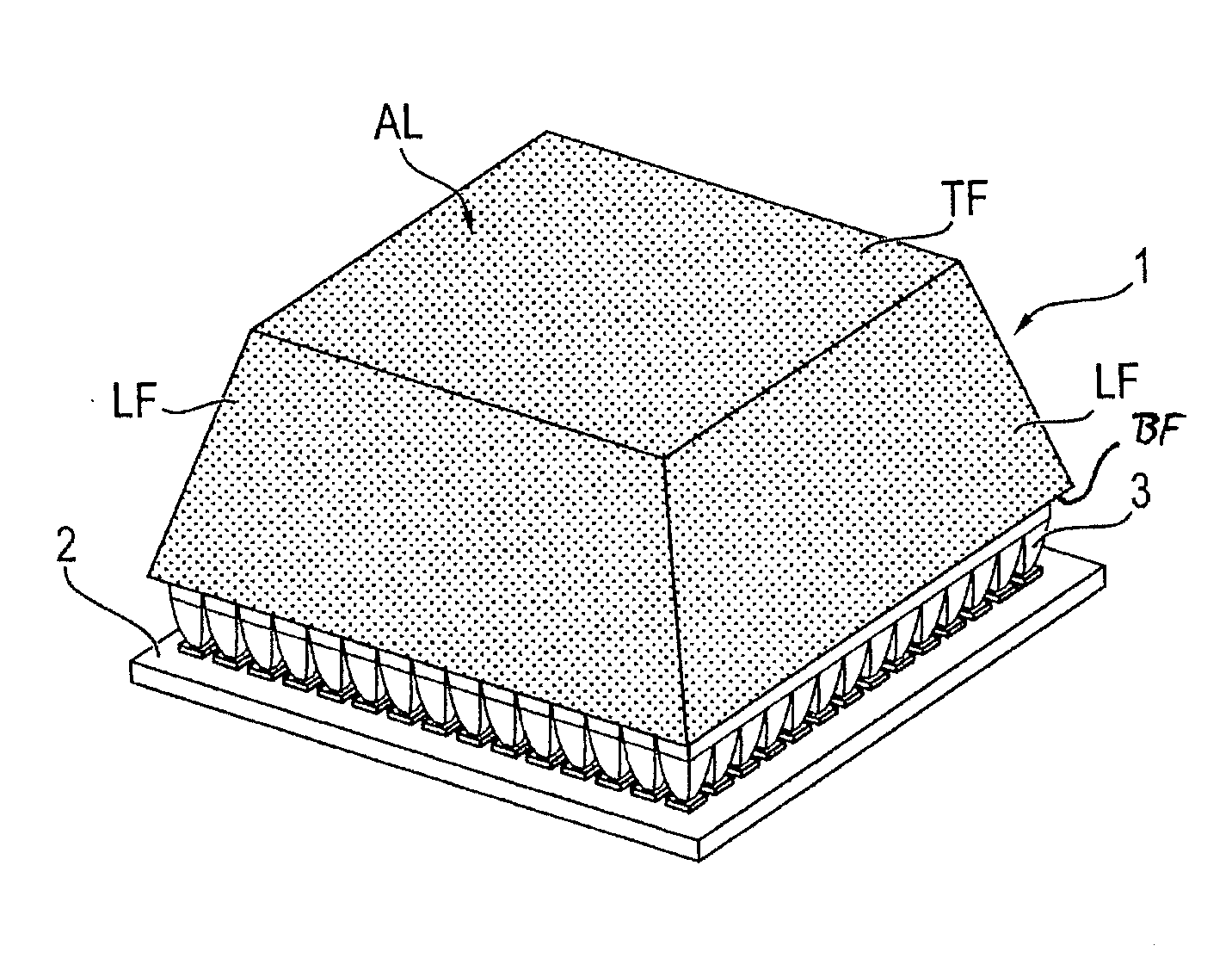
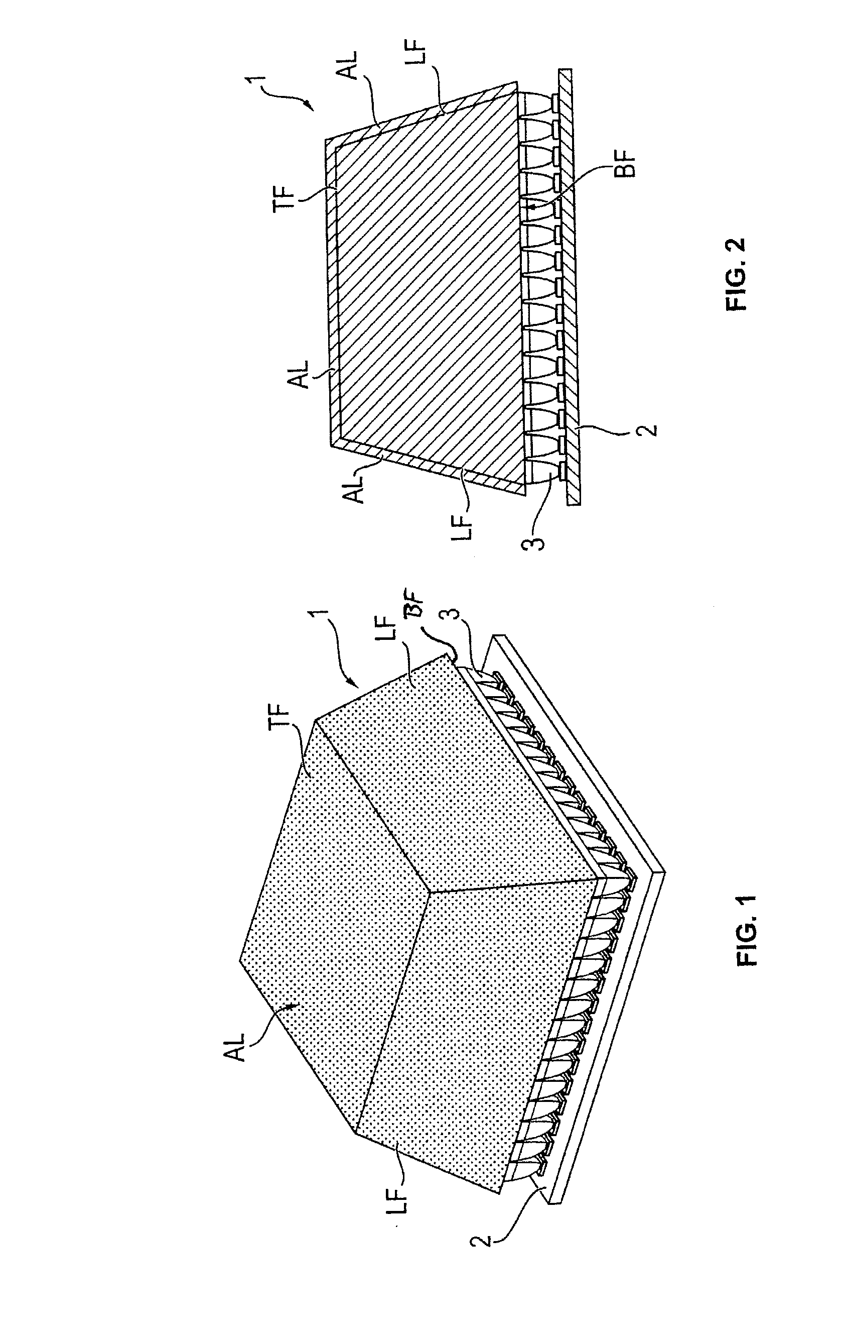
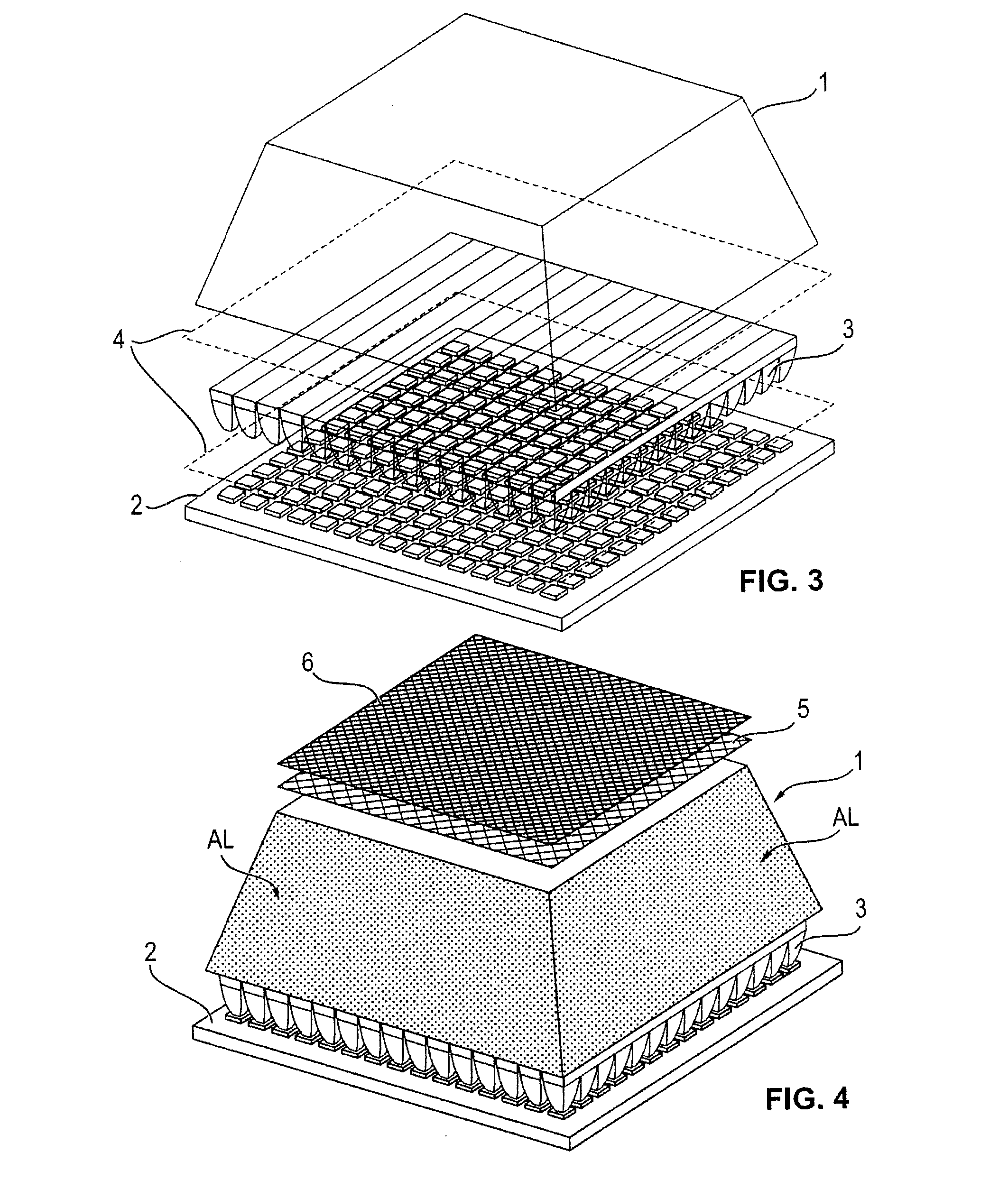
[0059]FIG. 1 shows an embodiment, wherein the scintillator 1 is a mono crystal having a truncated pyramid shape with all faces except the bottom base face BF (better visible in FIG. 2) covered with an absorbing layer AL and wherein a scintillation-light-incidence-angle-constraining (SLIAC) element, e.g. an array of concentrators 3, is optically coupled to the scintillation light transparent bottom face of the truncated pyramid mono crystal scintillator in order to guide the scintillation light onto a position sensitive photo sensor 2. Two of four lateral faces LF and the top base face TF are visible. The area of the top base face TF is smaller than the area of the bottom base face BF.

[0060]At this point, we also like to note that when referring to optic coupling of optical elements, we refer to the use of an optical medium such as silicone, grease or gel, thermal plastic or any other suitable material with a refraction index that reduces internal reflections, especially reflections ...


PUM


Abstract

An apparatus to detect gamma rays, comprising a scintillator, a position sensitive photo sensor and a scintillation-light-incidence-angle-constraining, SLIAC, element, the scintillator has faces and the position sensitive photo sensor detects scintillation photons exiting a scintillation photons transparent face of the scintillator, and a portion of a scintillator face is covered with an absorbing layer, which absorbs scintillation photons created by scintillation events due to the interaction of incoming gamma rays with the scintillator, and the SLIAC element is optically coupled between a scintillation photons transparent face of the scintillator and the position sensitive photo sensor and the SLIAC element guides the scintillation photons exiting the scintillator towards the position sensitive photo sensor, and the SLIAC element restricts the maximum allowed half light acceptance angle for the scintillation light hitting the position sensitive photo sensor to less than 45°.

Description

FIELD OF THE INVENTION[0001]The invention relates to the design of scintillation detectors as used in Nuclear imaging systems like Single-Photon Emission Computed Tomography (SPECT) or Positron Emission Tomography (PET) for the purpose of medical diagnosis.[0002]However it is to be understood that the present invention is also applicable in many other technical fields, as for example in astrophysical gamma ray telescopes or in examining rocks and minerals in geophysics.BACKGROUND OF THE INVENTION[0003]A wide range of medical image techniques is available for the diagnosis and treatment of diseases. One can differentiate between morphological imaging, such as in Computed Tomography (CT), Magnetic Resonance Imaging (MRI), X-ray, Ultrasound, etc. or functional imaging as in Gamma Ray Radiography, Single-Photon Emission Computed Tomography (SPECT) or Positron Emission Tomography (PET).[0004]Nuclear medicine is a special branch of medicine where physiological processes can be imaged by d...

Claims


Application Information

Patent Timeline
IPC IPC(8): G01T1/20
CPCG01T1/2002
Inventor BENLLOCH BAVIERA, JOSE MARIAGONZALEZ MARTINEZ, ANTONIO JAVIERSANCHEZ MARTINEZ, FILOMENOMOLINOS SONSONA, CESARCATRET MASCARELL, JUAN VICENTECORRECHER SALVADOR, CARLOSPAVON HERNANDEZ, NORIEL
Owner GENERAL EQUIP FOR MEDICAL IMAGING SL
Why Eureka
Try Eureka