Optical performance monitoring for D/WDM networks

a technology of optical performance monitoring and d/wdm network, applied in the field of optical transmission systems, can solve the problems of limited application of this method to high-speed d/wdm network, material scattering becomes an important factor, and the channel cross-talk between d/wdm systems is important, so as to reduce the current power estimation inaccuracy, reduce the sensitivity to system variables, and extend the bandwidth and transmission distance of the communication link.

Inactive Publication Date: 2005-07-26
CIENA
View PDF12 Cites 20 Cited by
  • Summary
  • Abstract
  • Description
  • Claims
  • Application Information

AI Technical Summary

Benefits of technology

[0025]The performance monitoring method according to the invention sufficiently decreases the current power estimation inaccuracy to yield acceptable equalization in many systems, and sufficiently compensates for the SRS-induced inaccuracies for systems with more than 20 channels. As a result, the compensation of the SRS induced error according to the invention extends the bandwidth and the transmission distance of the communication link.
[0026]In addition, the compensation method accounts for characteristics of the transport medium such as fiber type, fiber attenuation, number of wavelengths, number of spans, launch power, etc. It also accounts for the inaccuracy introduced by the elements present in the network, such as optical amplifiers, DCM (dispersion compensation module), etc. It results in a more robust estimation of power than the previous methods, and less sensitivity to system variables.

Problems solved by technology

Firstly, attenuation or transmission loss determines the maximum transmission distance before signal restoration is necessary.
Material scattering becomes an important problem at high powers and large number of wavelengths propagating along the same span of fiber.
SRS results in the energy from short wavelengths being transferred to longer wavelengths, which results in cross-talk between the channels in D / WDM systems.
However, application of this method to high-speed D / WDM networks is limited because of complexity of the circuitry needed to detect the dithers for each channel, when an increased number of optical carriers share a relatively narrow portion of the spectrum.
However, at very high speeds and systems having over 20 transmission channels, SRS induces Inaccuracies In the power estimate provided by AM-2.
Furthermore, this is a very expensive piece of equipment.

Method used


Image

  • Optical performance monitoring for D/WDM networks
  • Optical performance monitoring for D/WDM networks
  • Optical performance monitoring for D/WDM networks

Examples


Embodiment Construction

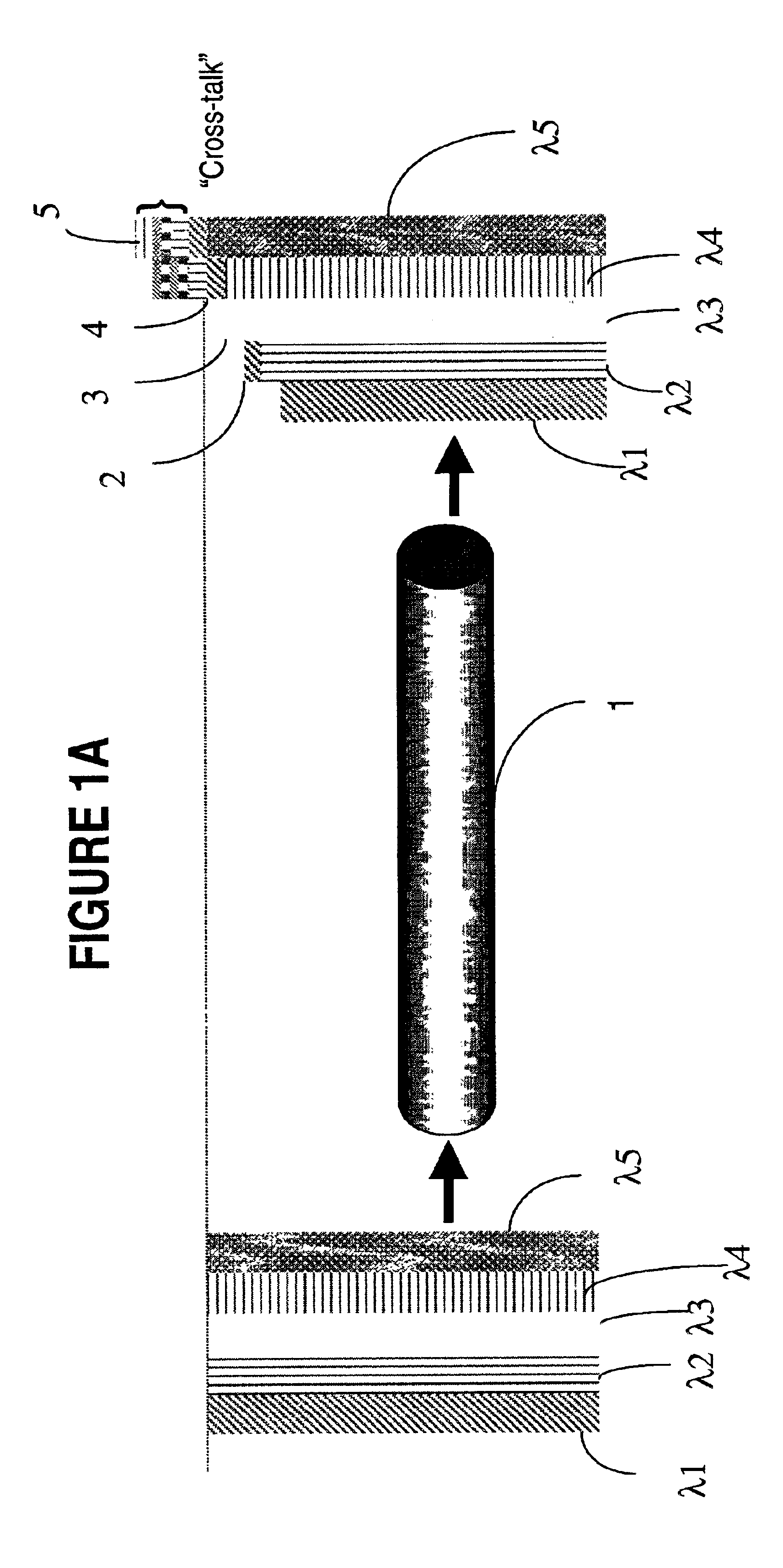
[0034]FIG. 1A illustrates intuitively how cross-talk between wavelengths occur due to SRS, for a five-channel example. It shows that all channels λ1-λ5 have the same power at the input side of fiber 1, and how power is transferred towards higher frequencies at the output of the fiber 1. Thus, channel λ2 has some information, denoted with 2, transferred through SRS from channel λ1, and channel λ3 carries some information, denoted with 3, transferred from channels λ1 and λ2 through SRS. The information denoted with 4 was transferred on channel λ4 from channels λ1, λ2 and λ3, and the information denoted with 5, was transferred on channel λ5 from channels λ1, λ2, λ3 and λ4.

[0035]It is evident on FIG. 1A that the cross-talk component on the higher wavelengths becomes larger as the number of channels grows. This is also consistent with EQ1.

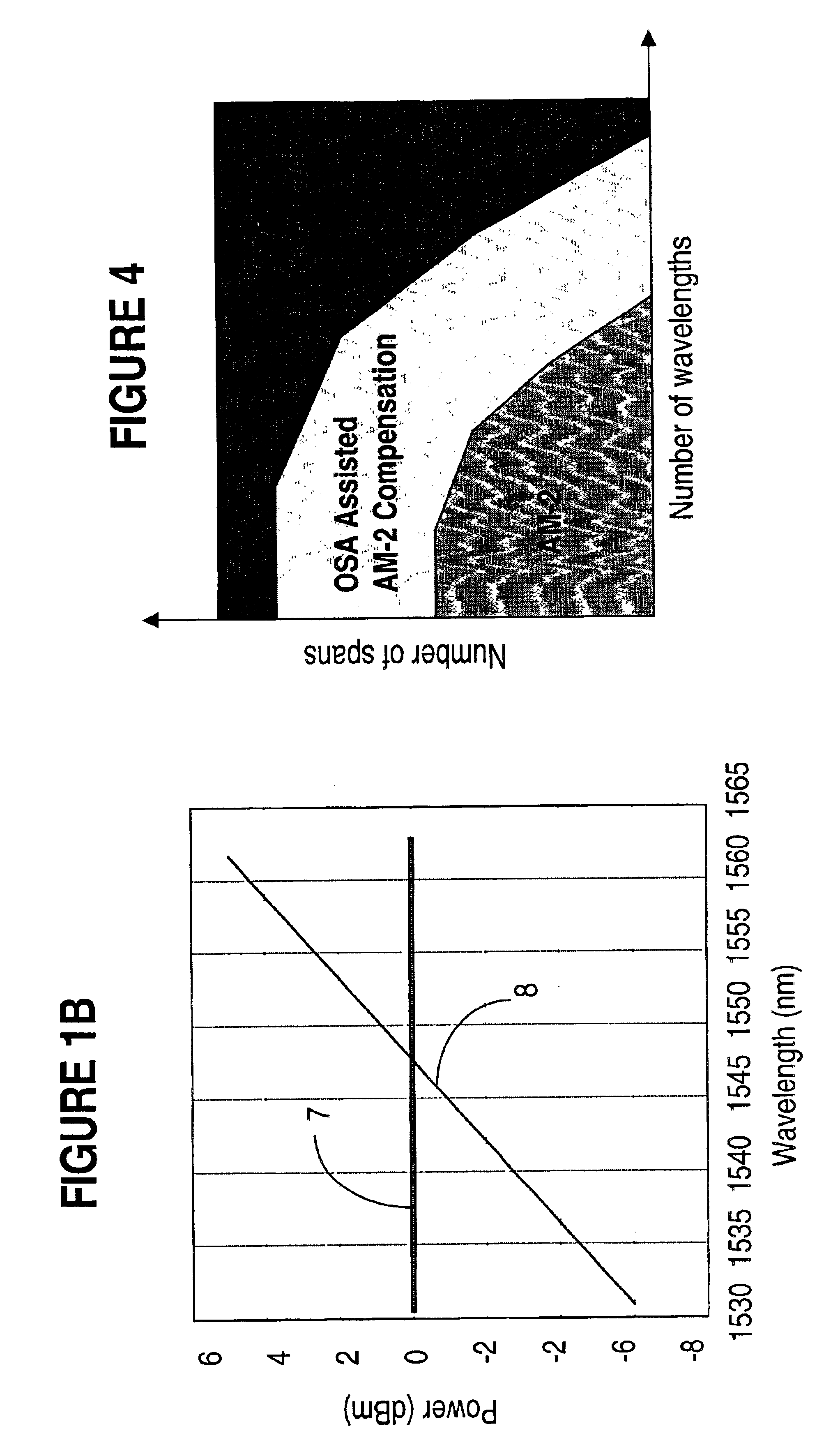
[0036]FIG. 1B shows the AC and DC power / wavelength transfer functions for a six-span link using non-shifted dispersion fiber (NSDF). The AC transfer fu...


PUM


Abstract

A performance monitoring method for an optically amplified transmission system. The method provides the optical power at each amplifier site, taking into account the inaccuracies introduced by the SRS in the power estimation obtained with the current methods. An optical spectrum analyzer is used at the output of the transmission link of interest to accurately measure the output power of each wavelength. This value is sent upstream to the last amplifier in the link, to compute an error term as the difference between the actual measurement and the estimation. The error term is used to infer the SRS-induced error by system elements not accounted for in the model. The error term is then fed-back to each amplifier in the link, so that the estimated power is adjusted to account for the SRS-induced inaccuracy.

Description

BACKGROUND OF THE INVENTION[0001]1. Field of the Invention[0002]This invention relates to optical transmission systems, and in particular to optical performance monitoring for wavelength division multiplexed (WDM) and dense WDM (DWDM) networks.[0003]2. Background Art[0004]Performance monitoring (PM) refers to in-service, non-intrusive monitoring of transmission quality (GR-253-CORE, issue 2, December 1995). Performance monitoring provides indications regarding the success of attempts to solve a problem, allows to isolate and resolve the problem before it affects traffic, and to determine the entity responsible with the equipment affecting adversely the traffic quality.[0005]The signal power of an optical channel has proved to be one of the most important factors in controlling the performance of an amplified optical network. Firstly, attenuation or transmission loss determines the maximum transmission distance before signal restoration is necessary. Equally important for D / WDM long ...

Claims


Application Information

Patent Timeline
Patent Type & Authority Patents(United States)
IPC IPC(8): H04B10/18H04B10/08H01S3/00H04B10/07H04B10/079H04B10/2507H04B10/2537H04B10/2543H04B10/29H04B10/294H04J14/00H04J14/02
CPCH04B10/0775H04B10/07955H04B10/2537H04B2210/072H04B2210/078
Inventor SIMARD, FREDERICPARK, DAVID W.
Owner CIENA
Why Eureka
Try Eureka