Substrate cleaning and processing apparatus with magnetically controlled spin chuck holding pins

a technology of spin chuck and holding pin, which is applied in the direction of cleaning process and apparatus, cleaning using liquids, instruments, etc., can solve the problems of difficult uniform cleaning of the whole outer edge of the substrate, and achieve the effects of preventing processing defects, preventing contamination of the exposure device, and preventing defective patterns

Active Publication Date: 2009-05-14
SCREEN SEMICON SOLUTIONS CO LTD
View PDF6 Cites 22 Cited by
  • Summary
  • Abstract
  • Description
  • Claims
  • Application Information

AI Technical Summary

Benefits of technology

[0032]The cleaner is moved to the space by the cleaner moving mechanism, to come into contact with the outer edge of the substrate that rotates. This allows the whole outer edge of the substrate to be cleaned with the cleaner, allowing a contaminant that adheres to the outer edge of the substrate to be removed. As a result, it is possible to prevent processing defects from occurring in the substrate due to contamination at the outer edge of the substrate.
[0033]When the cleaning processing unit cleans the outer edge of the substrate before the exposure processing by the exposure device, it is possible to prevent contamination in the exposure device due to the contamination at the outer edge of the substrate and to prevent defective patterns such as a defective dimension and a defective shape. When the cleaning processing unit cleans the outer edge of the substrate after the exposure processing by the exposure device, it is possible to prevent development defects from occurring during development of an exposure pattern.
[0034]According to the present invention, it is possible to clean the whole of the outer edge of the substrate. This can prevent processing defects from occurring in the substrate due to the contamination at the outer edge of the substrate.

Problems solved by technology

In such a case, when the outer edge of the substrate is held by the plurality of holding pins, the whole of the outer edge of the substrate is difficult to uniformly clean.

Method used


Image

  • Substrate cleaning and processing apparatus with magnetically controlled spin chuck holding pins
  • Substrate cleaning and processing apparatus with magnetically controlled spin chuck holding pins
  • Substrate cleaning and processing apparatus with magnetically controlled spin chuck holding pins

Examples


first embodiment

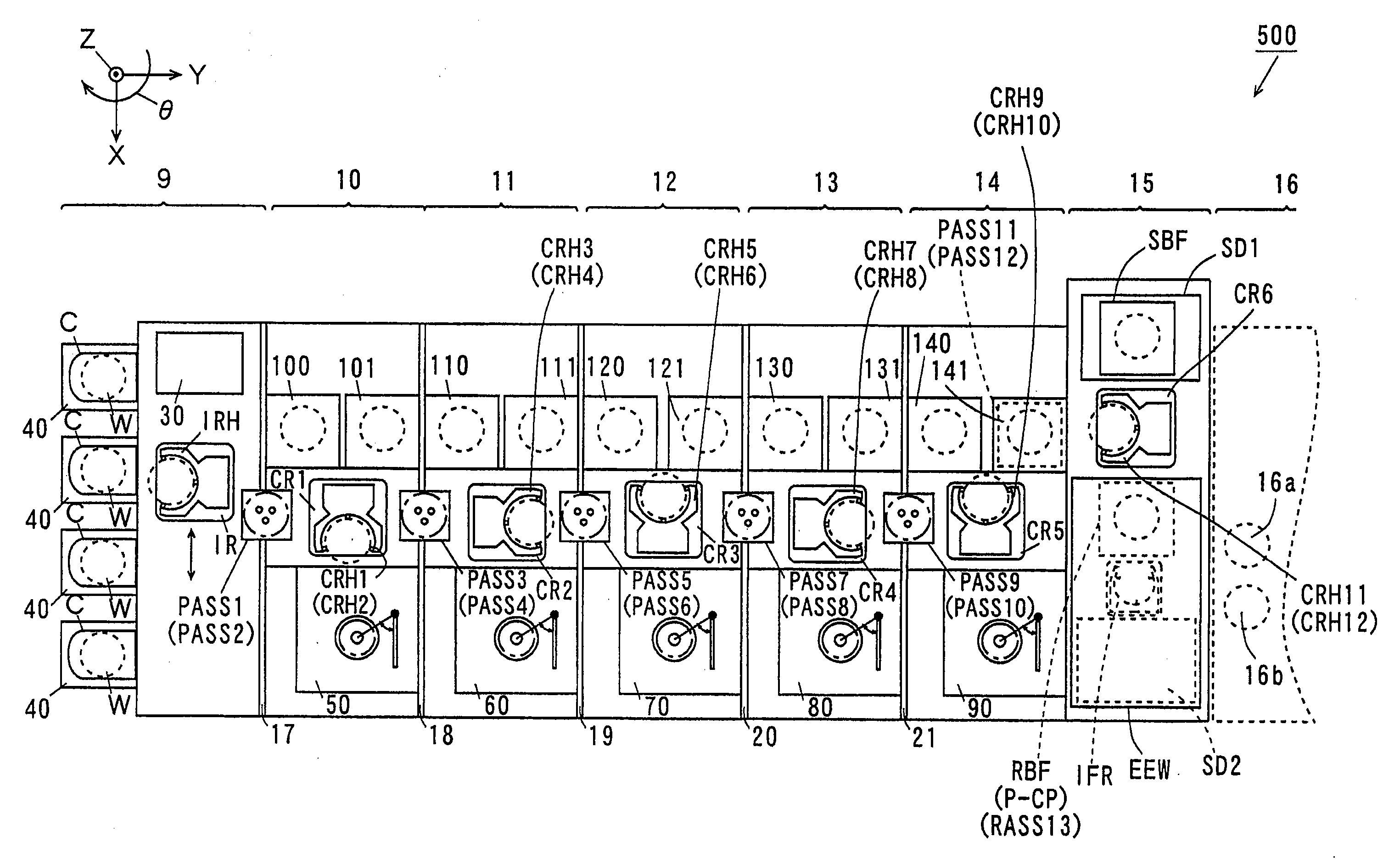
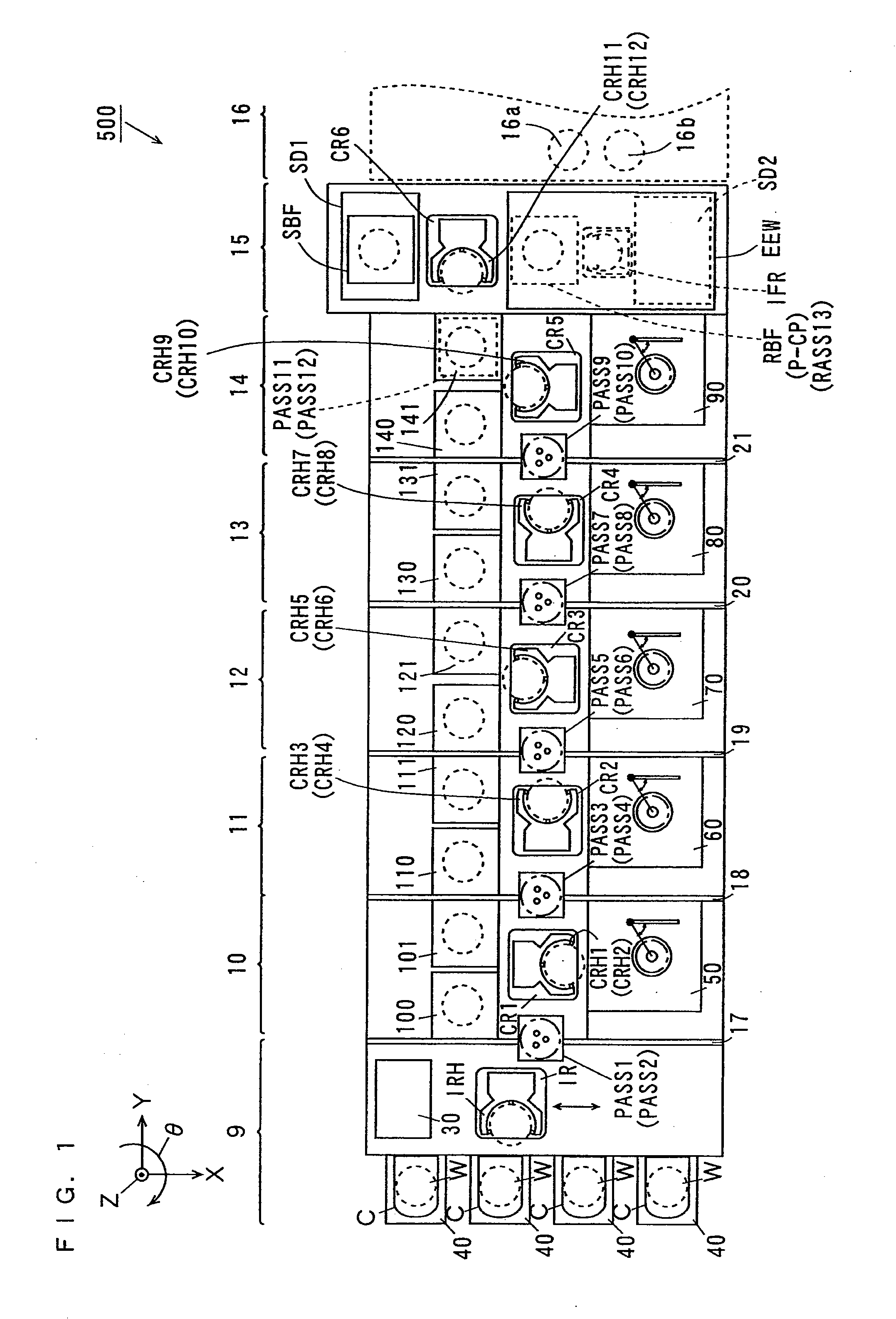
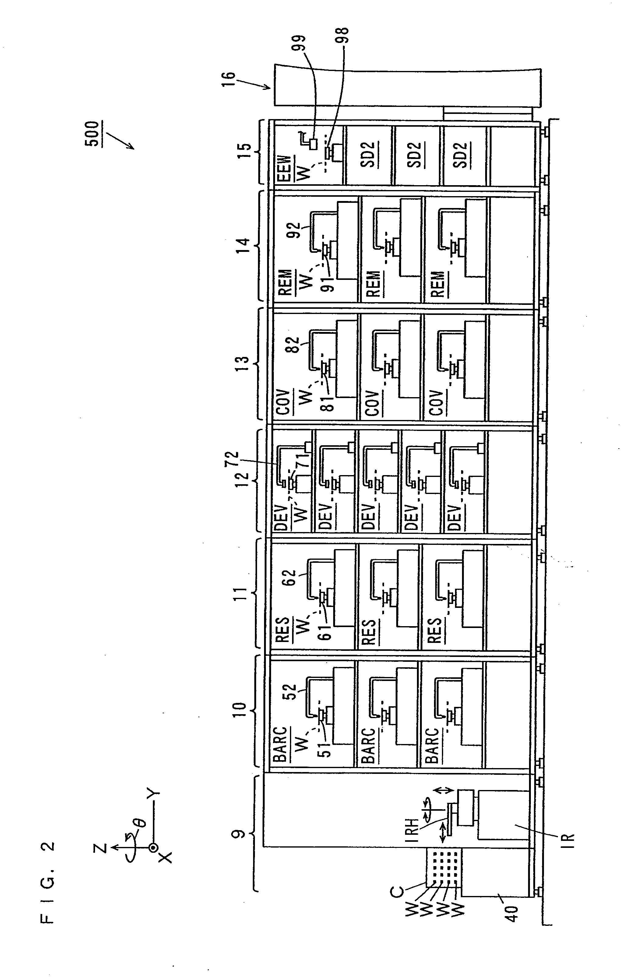
[0051]FIG. 1 is a plan view of a substrate processing apparatus according to the present invention. FIG. 1 and FIGS. 2 to 4 described later are accompanied by arrows that respectively indicate X, Y, and Z directions perpendicular to one another for clarity of a positional relationship. The X and Y directions are perpendicular to each other within a horizontal plane, and the Z direction corresponds to the vertical direction. In each of the directions, the direction of the arrow is defined as a + direction, and the opposite direction is defined as a − direction. A rotation direction centered around the Z direction is defined as a θ direction.

[0052]As shown in FIG. 1, a substrate processing apparatus 500 includes an indexer block 9, an anti-reflection film processing block 10, a resist film processing block 11, a development processing block 12, a resist cover film processing block 13, a resist cover film removal block 14, and an interface block 15. An exposure device 16 is arranged ad...

second embodiment

[0167]FIG. 11 is a plan view of a substrate processing apparatus according to the present invention. In the substrate processing apparatus, a substrate W is subjected to cleaning processing with various types of films not formed on the substrate W.

[0168]As shown in FIG. 11, a substrate processing apparatus 800 includes an indexer 810 and a cleaning processor 820. The indexer 810 is provided with a plurality of carrier platforms 811 and an indexer robot IRa. Carriers C that store a plurality of substrates W in a multiple stage are respectively carried onto the carrier platforms 811. The indexer robot IRa transports the substrate W between the carriers C and the cleaning processor 820.

[0169]A main robot MR is provided at the center of the cleaning processor 820. Substrate platforms PASS81 and PASS82 on which the substrate W is temporarily placed are provided one above the other between the main robot MR and the indexer 810. Furthermore, two cleaning processing units SS, a drying proce...


PUM

PropertyMeasurementUnit
temperatureaaaaaaaaaa
timeaaaaaaaaaa
magnetic forceaaaaaaaaaa

Abstract

When a substrate is subjected to bevel cleaning processing, a first magnet plate is arranged at a lower position, and a second magnet plate is arranged at an upper position. In this case, each of chuck pins enters a closed state in a region outside the first magnet plate, while entering an opened state in a region outside the second magnet plate. That is, a holder in each of the chuck pins is maintained in contact with an outer edge of the substrate when it passes through the region outside the first magnet plate, while being spaced apart from the outer edge of the substrate when it passes through the region outside the second magnet plate.

Description

CROSS-REFERENCES TO RELATED APPLICATIONS[0001]This application claims priority to Japanese Patent Application 2007-294072, filed Nov. 13, 2007. The disclosure of JP 2007-294072 is hereby incorporated by reference in its entirety for all purposes.BACKGROUND OF THE INVENTION[0002]The present invention relates to a substrate holding and rotating device that rotates a substrate while holding the substrate, and a substrate cleaning apparatus and a substrate processing apparatus including the same.[0003]Substrate processing apparatuses have been conventionally used to subject substrates such as semiconductor wafers, and glass substrates for photomasks, liquid crystal displays, and optical disks to various types of processing.[0004]In the substrate processing apparatuses, the substrates are subjected to cleaning processing with the substrates held by spin chucks. Examples of the spin chucks include end surface holding type spin chucks that hold outer edges of the substrates (see, for examp...

Claims


Application Information

Patent Timeline
Patent Type & Authority Applications(United States)
IPC IPC(8): B08B13/00B08B1/02G03F1/82H01L21/304
CPCH01L21/67046H01L21/67051H01L21/6715Y10S134/902H01L21/67178H01L21/68728H01L21/68742H01L21/67173H01L21/302H01L21/683
Inventor NISHIYAMA, KOJIYOSHII, HIROSHI
Owner SCREEN SEMICON SOLUTIONS CO LTD
Why Eureka
Try Eureka