Tapered roller bearing and method of designing the same

a tapered roller bearing and rolling surface technology, applied in the direction of roller bearings, mechanical equipment, instruments, etc., can solve the problems of increased grinding amount, machining defect, insufficient work of finishing grindstone, etc., to reduce the contact pressure and stress at the contact area, increase the long service life and reduce the cost

Active Publication Date: 2014-10-14
NTN CORP
View PDF16 Cites 7 Cited by
  • Summary
  • Abstract
  • Description
  • Claims
  • Application Information

AI Technical Summary

Benefits of technology

[0013]In view of the foregoing, an object of the present invention is to provide a tapered roller bearing assembly, in which not only the contact pressure but also the stress at the contact area is reduced to increase the working lifetime of the bearing assembly and, also, the machining defect, which would occur in the raceway surface, is kept from occurring to allow the drop amount at the opposite ends of each of the rollers to be reduced to thereby increase the machining efficiency. The present invention is also intended to provide a method of designing such roller bearing assembly.
[0016]According to the present invention, since the crowning profile is employed in the roller rolling surface in the outer periphery of the roller, as compared with the crowning profile employed only in the inner ring raceway surface, the grindstone can sufficiently work on the roller rolling surface to the extent needed. Accordingly, any possible processing defect to the rolling surface can be prevented. Thanks to the crowning profile formed in the roller rolling surface, the contact pressure and the stress at the contact area can be reduced to increase the working lifetime of the tapered roller bearing assembly. Also, since the curvature of the generatrix of the non-contact area crowned portion in the vicinity of the point of connection between the contact area crowned portion and the non-contact area crowned portion is smaller than the curvature of the generatrix of the contact area crowned portion, the drop amount at each of the opposite ends of the roller can be reduced. Accordingly, the grinding amount can be suppressed as compared with that in, for example, the single arcuate crowning profile hitherto employed and the machining efficiency of the roller can be increased to allow the cost of manufacture to be reduced.
[0019]A portion or the whole of the generatrix of the contact area crowned portion referred to above may be represented by a logarithmic crowning profile. Thanks to the contact area crowned portion expressed by the logarithmic crowning profile, the contact pressure and the stress at the contact area can be reduced to increase the service life of the tapered roller bearing assembly.
[0022]Of the generatrix of the non-contact area crowned portion, a connection with a portion formed by a logarithmic curve of the logarithmic crowning profile may be matched with the gradient of the logarithmic curve. In such case, the generatrix of the contact area crowned portion and the generatrix of the non-contact area crowned portion can be continued further smoothly at the point of connection.
[0038]According to the designing method of the present invention, the tapered roller bearing assembly capable of reducing the contact pressure and the stress at the contact area to increase the long service life can be designed easily. Also, the tapered roller bearing assembly of a kind that can be manufactured at a reduced cost while the drop amount is reduced can be designed.

Problems solved by technology

If the crowning profile expressed by the logarithmic function (which profile is hereinafter referred to as “logarithmic crowning profile”) is employed in the inner ring, there is a likelihood that because of the presence of collars each at one end of the raceway surface defined in the inner ring with respect to the axial direction of the inner ring, the finishing grindstone will not work sufficiently on areas of the raceway surface adjacent the opposite ends thereof, where the amount of drop in finishing the crowning profile is large, resulting in a machining defect.
It has, however, been found that the conventional design of the logarithmic crowning profile results in that the entire crowning profile is expressed by the logarithmic curve and, therefore, the amount of drop at the opposite ends each of the rollers, where the rollers does not contact the inner ring, is larger than needed, resulting in an increase of the grinding amount.
Even with the crowning profile depicted by a single arcuate line (an arc), the drop amount tends to become excessive at the roller opposite ends.

Method used


Image

  • Tapered roller bearing and method of designing the same
  • Tapered roller bearing and method of designing the same
  • Tapered roller bearing and method of designing the same

Examples


first embodiment

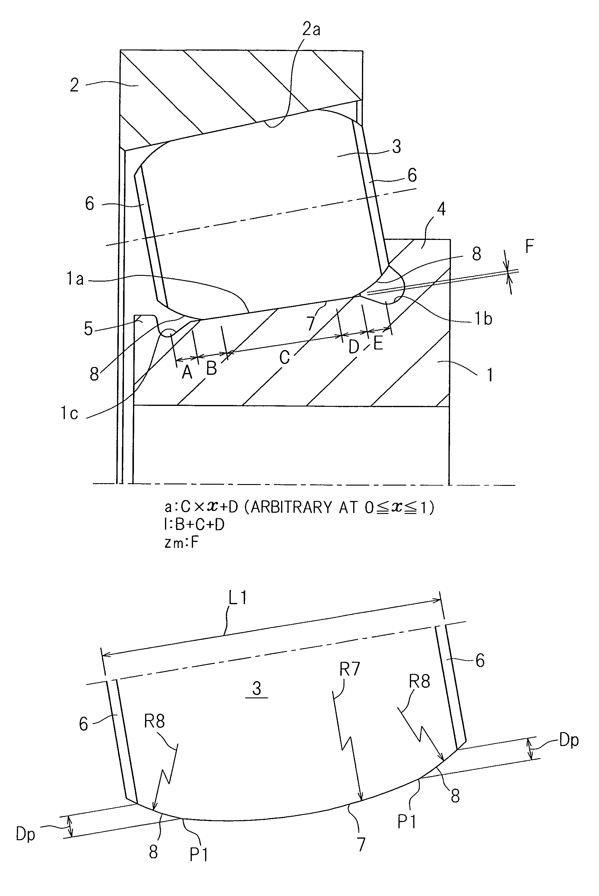
[0048]The tapered roller bearing assembly according to the present invention includes, as best shown in FIG. 1, an inner ring 1, an outer ring 2 and a plurality of tapered rollers 3 between the inner ring 1 and the outer ring 2. The inner ring 1 has an outer periphery formed with an inner ring raceway surface 1a having a radially outwardly protruding large collar 4, defined at a large diameter side thereof, and a radially outwardly protruding small collar 5 defined at a small diameter side thereof. A corner area delimited between the inner ring raceway surface 1a and the large collar 4 has a generally radially inwardly depressed, first grinding undercut 1b defined therein and the opposite corner area delimited between the inner ring raceway surface 1a and the small collar 5 similarly has a generally radially inwardly depressed, second grinding undercut 1c defined therein. The inner ring raceway surface 1a has its generatrix extending in a direction axially of the inner ring 1, which...

second embodiment

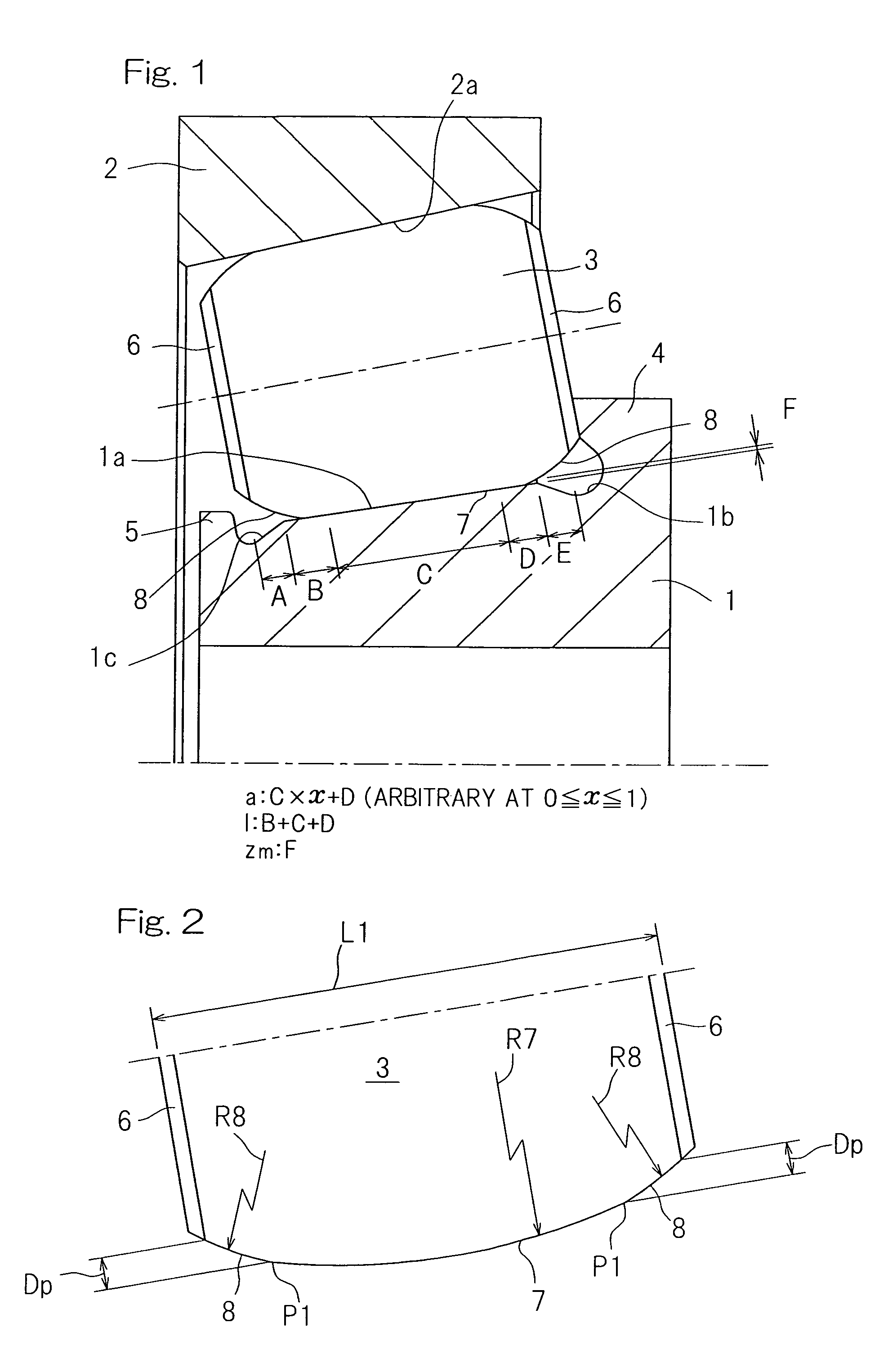
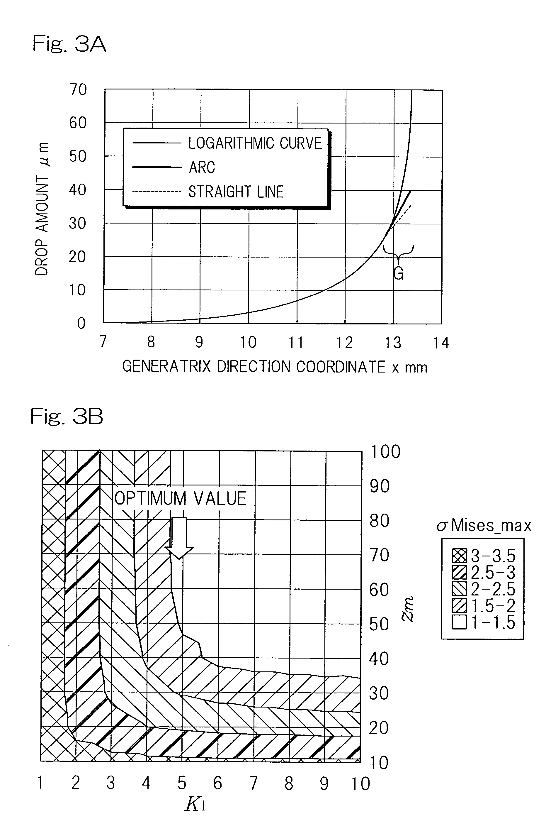
[0074]The generatrix of the non-contact area crowned portion 8 may have one or both of portions at the large and small diameter sides, which is / are represented by an arcuate line. In such case, rather than the generatrix of the roller rolling surface in its entirety expressed by, for example, a logarithmic curve, the drop amount Dp can be reduced. Accordingly, the grinding amount can be reduced. As is the case with a second preferred embodiment of the present invention as shown in FIG. 4, the generatrix of the non-contact area crowned portion 8 referred to above may have one or both of portions at the large and small diameter sides, which is / are represented by a straight line. (In the case of the present invention shown in FIG. 4, that portion of the generatrix of the non-contact area crowned portion 8 at only the large diameter side is represented by the straight line.) In such case, the drop amount Dp can be further reduced as compared with that afforded when the generatrix of the...


PUM


Abstract

In a tapered roller bearing assembly, a crowning profile formed portion of the roller rolling surface is made up of a contact area crowned portion, which is held in contact with an inner ring raceway surface, and a non-contact area crowned portion which is held in non-contact with the inner ring raceway surface. The contact area crowned portion and the non-contact area crowned portion have their generatrices extending in an axial direction of a roller, which generatrices are represented by corresponding continuous lines represented by different functions and continued smoothly at a point of connection, and the curvature of the generatrix of the non-contact area crowned portion in the vicinity of the connection point is chosen to be smaller than the curvature of the generatrix of the contact area crowned portion.

Description

CROSS REFERENCE TO RELATED APPLICATIONS[0001]This application claims the benefit under 35 U.S.C. Section 371, of PCT International Application No. PCT / JP2010 / 056828, filed Apr. 16, 2010, which claimed priority to Japanese Application No. 2009-105854, filed Apr. 24, 2009 in the Japanese Patent Office, the disclosures of which are hereby incorporated by reference.BACKGROUND OF THE INVENTION[0002]1. Field of the Invention[0003]The present invention relates to a tapered roller bearing for supporting a rotating component of various machines and equipments and a method of designing the same. More particularly, the present invention relates to a crowning profile of a roller rolling surface in the tapered roller bearing.[0004]2. Description of Related Art[0005]The crowning profile in the tapered bearing assembly may be defined in any one of an inner ring, an outer ring and a plurality of rolling elements (rollers), and suggestions have been hitherto made to define the principal crowning pro...

Claims


Application Information

Patent Timeline
Patent Type & Authority Patents(United States)
IPC IPC(8): F16C19/36F16C33/58F16C33/36
CPCF16C33/36F16C19/364F16C2240/50
Inventor FUJIWARA, HIROKI
Owner NTN CORP
Why Eureka
Try Eureka