Sound absorbing structure and sound chamber

a sound absorber and structure technology, applied in the direction of instruments, building roofs, electric apparatus casings/cabinets/drawers, etc., can solve the problem of difficulty in forming an air layer having an adequate thickness, and achieve the effect of reducing thickness and efficient sound absorption

Active Publication Date: 2009-05-14
YAMAHA CORP
View PDF62 Cites 18 Cited by
  • Summary
  • Abstract
  • Description
  • Claims
  • Application Information

AI Technical Summary

Benefits of technology

[0009]It is an object of the present invention to provide a sound absorbing structure which is capable of efficiently absorbing low-frequency sound with a reduced thickness of an air layer.
[0019]The sound absorbing structure of the present invention can efficiently absorb sound particularly in low frequencies, wherein the air layer of the sound absorber can be reduced in thickness.

Problems solved by technology

This makes it difficult to form an air layer having an adequate thickness.

Method used


Image

  • Sound absorbing structure and sound chamber
  • Sound absorbing structure and sound chamber
  • Sound absorbing structure and sound chamber

Examples


first embodiment

1. First Embodiment

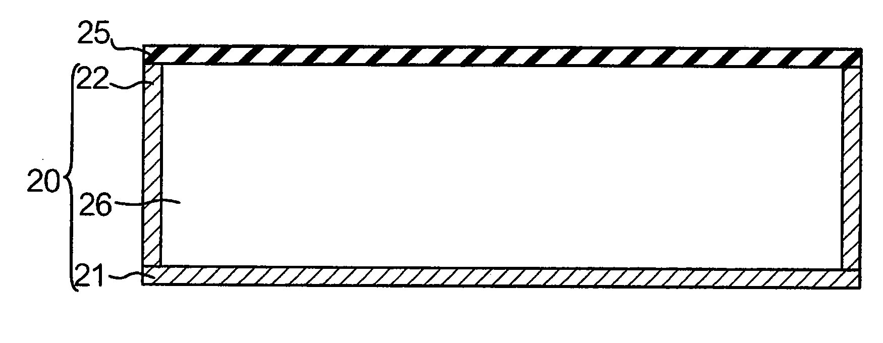
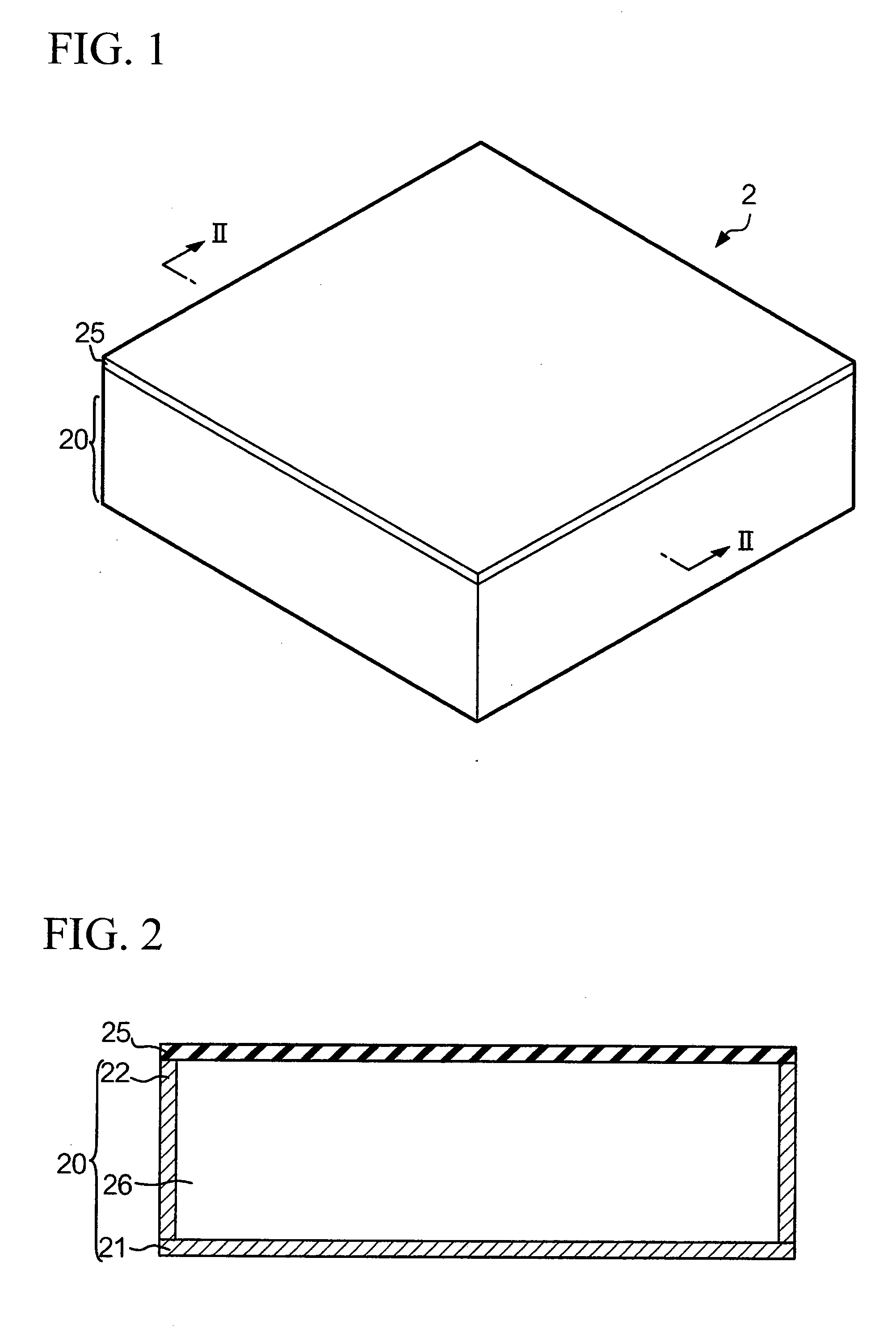
[0042]FIG. 1 is a perspective view showing the exterior of a sound absorber in accordance with the first embodiment of the present invention; FIG. 2 is a cross-sectional view of the sound absorber 2 taken along line II-II in FIG. 1. The sound absorber 2 is constituted of a housing 20 and a vibration member 25. The housing 20 is composed of wooden materials and is constituted of a bottom member 21 (corresponding to the bottom of the sound absorber 2) having a rectangular shape and a side wall member 22 (forming the side wall of the housing 20), thus forming an internal space which allows the vibration member 25 to vibrate. The side wall member 22 is a rectangular timber having openings, wherein the edge of one opening thereof is fixed to the bottom member 21. The housing 20 is not necessarily composed of wooden materials but can be formed using other materials such as synthetic resins and metals having high rigidities enough for the vibration member 25 to vibrate.

[...

second embodiment

2. Second Embodiment

[0114]The sound absorber 2 can be further modified in a variety of ways other than the first embodiment and variations in accordance with a second embodiment of the present invention; hence, variations of the second embodiment will be described with reference to FIGS. 14 to 18, wherein parts identical to those shown in FIGS. 1 to 3 are designated by the same reference numerals.

(1) First Variation

[0115]FIG. 14 shows a first variation of the second embodiment, in which a porous layer 27 (composed of a porous material) is attached to the exterior surface of the sound absorber 2 opposite to the vibration member 25, i.e. the exterior surface of the housing 20 opposite to the surface of the vibration member 25 directly facing the boundary of the room, such as the surface of the bottom member 21. The porous layer 27 absorbs sound at intermediate and higher frequencies. That is, the sound absorber 2 shown in FIG. 14 may function in a similar manner to the sound absorber ...


PUM


Abstract

A sound absorber is formed by covering the opening of a housing with a vibration member having a flat shape or a film shape so as to define an air layer therebetween. The sound absorber is attached to the wall of a room such that the vibration member is positioned opposite to the wall with a prescribed space therebetween. Sound generated in the room particularly in low frequencies enters into the space between the vibration member and the wall so as to cause vibration of the vibration member due to the pressure difference between the sound pressure applied to the space and the internal pressure of the air layer, thus consuming energy of sound waves. Thus, it is possible to efficiently absorb low-frequency sound with a reduced thickness of the air layer.

Description

BACKGROUND OF THE INVENTION[0001]1. Field of the Invention[0002]The present invention relates to sound absorbing structures for absorbing sounds in sound chambers.[0003]The present application claims priority on Japanese Patent Application No. 2007-265554, the content of which is incorporated herein by reference.[0004]2. Description of the Related Art[0005]Various types of sound absorbing structures having air layers between sound absorbers and walls of chambers (or rooms) have been developed and are disclosed in various documents such as Patent Document 1.[0006]Patent Document 1: Japanese Unexamined Patent Application Publication No. H05-231177[0007]Patent Document 1 teaches a soundproof device having a sound absorbing structure, wherein a sound absorbing panel, in which square-shaped sound absorbers composed of ceramics are aligned to form irregular surfaces (having recesses and projections), is disposed to form an air layer with a side wall. In this sound absorbing structure, sou...

Claims


Application Information

Patent Timeline
Patent Type & Authority Applications(United States)
IPC IPC(8): E04B1/84
CPCG10K11/172E04B1/8404
Inventor TANASE, RENTO
Owner YAMAHA CORP
Why Eureka
Try Eureka