Ventilation Member, Ventilation Member Kit, and Vented Housing and Vented Tank Using Them

a technology of ventilation member and kit, which is applied in the direction of check valves, rigid containers, packaging, etc., can solve the problems of reduced light intensity of light emitted from the lamp, high humidity of the exterior housing, and prone to fogging, so as to reduce the amount of water vapor, shorten the time, and prolong the time

Active Publication Date: 2009-05-14
NITTO DENKO CORP
View PDF10 Cites 14 Cited by
  • Summary
  • Abstract
  • Description
  • Claims
  • Application Information

AI Technical Summary

Benefits of technology

[0006]When such a conventional ventilation member is attached to a tank (such as a bottle for chemicals, an organic solvent tank, and a gas tank), it is possible to obtain similar advantageous effects to those in the case where the ventilation member is attached to the housing, while preventing the entry of water, dust, and the like into the tank.
[0007]However, when the conventional ventilation member 101 is attached to a tank, the gas inside the tank and the gas outside the tank are in communication with each other via the gas permeable membrane 102 at all times, as in the case where the conventional ventilation member 101 is attached to the housing 105. Consequently, water vapor outside the tank may enter the interior of the tank, causing adverse effects on the liquid accommodated in the tank or causing moisture to accumulate in the tank.DISCLOSURE OF THE INVENTION
[0008]Accordingly, it is an object of the present invention to provide a ventilation member that can extend the time until fogging will be produced in the housing and shorten the time until the produced fogging will be cleared up even when the interior of the housing has been fogged, by allowing the ventilation member to have a structure that has not been available before. It is also an object of the invention to provide a vented housing using the just-mentioned ventilation member.
[0009]It is also an object of the present invention to provide a ventilation member that can reduce the amount of water vapor entering the interior of a tank and can discharge the gas in the tank quickly to the exterior of the tank when the pressure inside the tank increases, by allowing the ventilation member to have a structure that has not been available before. It is also an object of the invention to provide a vented tank that uses the just-mentioned ventilation member.
[0010]A ventilation member according to the present invention includes: a first gas permeable membrane, a second gas permeable membrane, and an absorbing layer allowing a gas passing through an opening of a housing or a tank to permeate therethrough, with the ventilation member being fixed to the opening; a support body for supporting the first gas permeable membrane, the second gas permeable membrane, and the absorbing layer; and a first one-way valve disposed so as to cover the first gas permeable membrane. The first gas permeable membrane and the second gas permeable membrane are disposed in such a manner that the gas permeates through the gas permeable membranes independently of each other. The second gas permeable membrane and the absorbing layer are disposed in such a manner that the gas permeates through the second gas permeable membrane and the absorbing layer successively. The absorbing layer contains a water absorbent.
[0011]A ventilation member kit according to the present invention includes: a first ventilation member comprising a first gas permeable membrane allowing a gas passing through a first opening of a housing or a tank to permeate therethrough, with the first ventilation member being fixed to the first opening, a first support body for supporting the first gas permeable membrane, and a first one-way valve disposed so as to cover the first gas permeable membrane; and a second ventilation member comprising a second gas permeable membrane and an absorbing layer allowing a gas passing through a second opening of the housing or the tank to permeate therethrough, with the second ventilation member being fixed to the second opening, and a second support body for supporting the second gas permeable membrane and the absorbing layer, wherein in the second ventilation member, the second gas permeable membrane and the absorbing layer are disposed in such a manner that the gas permeates through the second gas permeable membrane and the absorbing layer successively, and the absorbing layer contains a water absorbent.

Problems solved by technology

For example, when the housing is a lamp that is one type of automobile electrical components, the water droplets (fogging) can become a cause of reducing the light intensity of the light emitted from the lamp.
Such fogging is apt to occur by turning off the lamp when the air temperature is low and the humidity of the exterior the housing is high (for example, when it is raining or snowing in winter).
It is possible to delay the generation of water droplets (production of fogging) by reducing the gas permeable area of the gas permeable membrane provided for the ventilation member to decrease the amount of the water vapor that enters the interior of the housing per unit time; however, in this method, the amount of the water vapor discharged to the exterior of the housing per unit time also decreases simultaneously, and therefore, it takes a long time before the generated water droplets disappear (i.e., until fogging will be cleared up).
In addition, when electricity is passed through an electrical component, such as a lamp, in which the interior of the housing heats up during electricity application, when fogging has been produced therein, the water droplets are heated and water vapor is produced; however, the ventilation member provided with a gas permeable membrane having a small gas permeable area requires a long time to release the produced water vapor to the exterior of the housing.
Consequently, water vapor outside the tank may enter the interior of the tank, causing adverse effects on the liquid accommodated in the tank or causing moisture to accumulate in the tank.

Method used


Image

  • Ventilation Member, Ventilation Member Kit, and Vented Housing and Vented Tank Using Them
  • Ventilation Member, Ventilation Member Kit, and Vented Housing and Vented Tank Using Them
  • Ventilation Member, Ventilation Member Kit, and Vented Housing and Vented Tank Using Them

Examples


examples

[0105]Hereinbelow, the present invention will be described in detail with reference to examples. It should be understood, however, that the invention is not limited by the following examples.

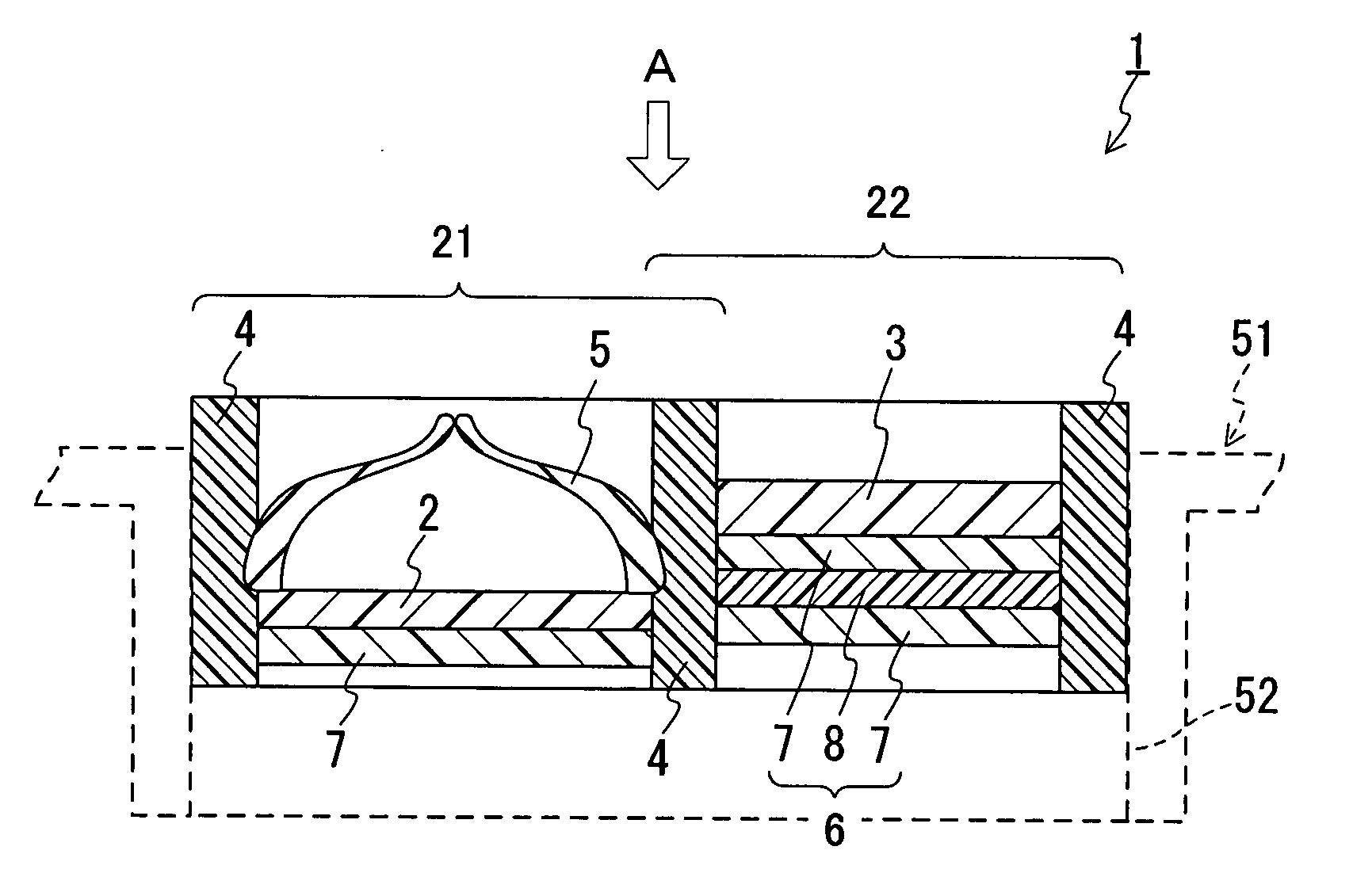
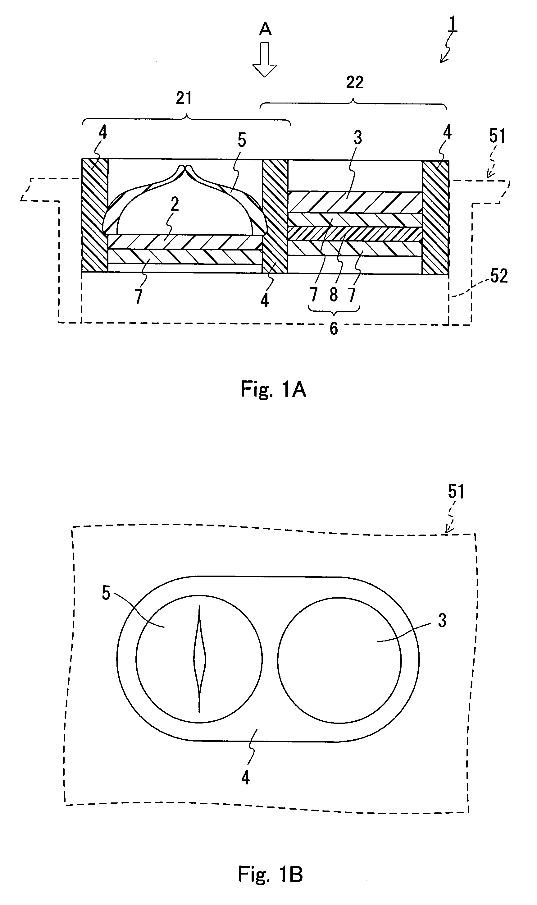
[0106]In the present examples, five types of the ventilation members that have a structure as shown in FIG. 1 as the example samples and three types of comparative example samples were fabricated to evaluate the fogging characteristic, the fogging clearing characteristic, and the pressure difference eliminating characteristic for each of the ventilation member samples when fixed to an automobile lamp.

[0107]First, manufacturing methods for the samples of the ventilation members will be described.

[0108]Sample 1

[0109]First, a support body 4 as shown in FIG. 1 that has two holes (one of the holes, hole A had a diameter of 16 mmΦ, and the other one, hole B had a diameter of 10 mmΦ) for placing gas permeable membranes therein was molded using a thermoplastic elastomer (“Milastomer 6030” made by Mitsui...


PUM


Abstract

A ventilation member and a ventilation member kit are provided that can extend the time until fogging will be produced in a housing and also can shorten the time until the produced fogging will be cleared up even when the interior of the housing has been fogged. A vented housing and a vented tank using them are also provided. A ventilation member includes: a first gas permeable membrane, a second gas permeable membrane, and an absorbing layer allowing a gas passing through an opening of a housing or a tank to permeate therethrough, with the ventilation member being fixed to the opening; a support body for supporting the first gas permeable membrane, the second gas permeable membrane, and the absorbing layer; and a first one-way valve disposed so as to cover the first gas permeable membrane. The first gas permeable membrane and the second gas permeable membrane are disposed in such a manner that the gas permeates through the gas permeable membranes independently of each other. The second gas permeable membrane and the absorbing layer are disposed in such a manner that the gas permeates through the second gas permeable membrane and the absorbing layer successively. The absorbing layer contains a water absorbent.

Description

TECHNICAL FIELD[0001]The present invention relates to a ventilation member and a ventilation member kit that are fixed to a tank, or to a housing for electrical components (typically automobile electrical components) for ensuring ventilation between the interior and the exterior of the tank or the housing and suppressing the entry of foreign matter into the interior of the tank or the housing. The invention also relates to a vented housing and a vented tank in which the ventilation member and / or the ventilation member kit is / are fixed.BACKGROUND ART[0002]Conventionally, ventilation members are attached to housings of electric appliances such as mobile telephones, cameras, and of automobile electrical components including lamps, pressure sensors, and ECUs (Electrical Control Units), in order to ensure ventilation between the interior and the exterior of the housings and to prevent the entry of foreign matter into the interior of the housings. Attaching such ventilation members to the...

Claims


Application Information

Patent Timeline
Patent Type & Authority Applications(United States)
IPC IPC(8): B65D90/34F24F7/00
CPCB01D53/261F16K15/145F21V31/03F16K24/00F21S48/335F16K15/148F21S45/30Y10T137/7838Y10T137/7882H05K5/0216B60R16/02B01D53/263B01D53/28H05K5/0213
Inventor MASHIKO, HIROAKI
Owner NITTO DENKO CORP
Why Eureka
Try Eureka