Sensor tag, sensor tag device, power receiving circuit, and sensor tag device power supply method

a technology of sensor tags and power supply methods, applied in the field of sensor tags, can solve the problems of increasing the amount of battery consumption, and achieve the effects of ensuring long wireless communication distances, and improving the receiving efficiency of transmission/reception antennas

Inactive Publication Date: 2009-05-14
KITAYOSHI HITOSHI +1
View PDF24 Cites 24 Cited by
  • Summary
  • Abstract
  • Description
  • Claims
  • Application Information

AI Technical Summary

Benefits of technology

[0037]According to the invention defined in claim 1, since charging and communication based on electromagnetic induction do not have to be performed, a long wireless communication distance can be assured.
[0038]According to the invention defined in claim 2, a receiving efficiency of the transmission / reception antenna can be improved.
[0039]According to the invention defined in claim 3, the receiving efficiency of the transmission / reception antenna can be further improved.
[0040]According to the invention defined in claim 4, since the power receiving circuit and the ASK demodulation circuit can be used in common, a circuit configuration can be simplified, and a utility value of a received electric wave energy can be increased.
[0041]According to the invention defined in claim 5, a general-purpose product can be used as the microprocessor, the microprocessor can be operated even if a driving power source with a lower power and a low load (e.g., 1.0 V and a load of 2 μA, i.e., approximately 500 KΩ) is adopted, and the wireless communication distance can be further increased with realization of a low power.
[0042]According to the invention defined in claim 6, operating conditions can be satisfied by increasing a power supply voltage and reducing an output impedance in accordance with a timing where a maximum power consumption is demanded.

Problems solved by technology

However, in this case, since an oscillation power is supplied from the battery 504, a consumption amount of the battery is increased

Method used


Image

  • Sensor tag, sensor tag device, power receiving circuit, and sensor tag device power supply method
  • Sensor tag, sensor tag device, power receiving circuit, and sensor tag device power supply method
  • Sensor tag, sensor tag device, power receiving circuit, and sensor tag device power supply method

Examples


Embodiment Construction

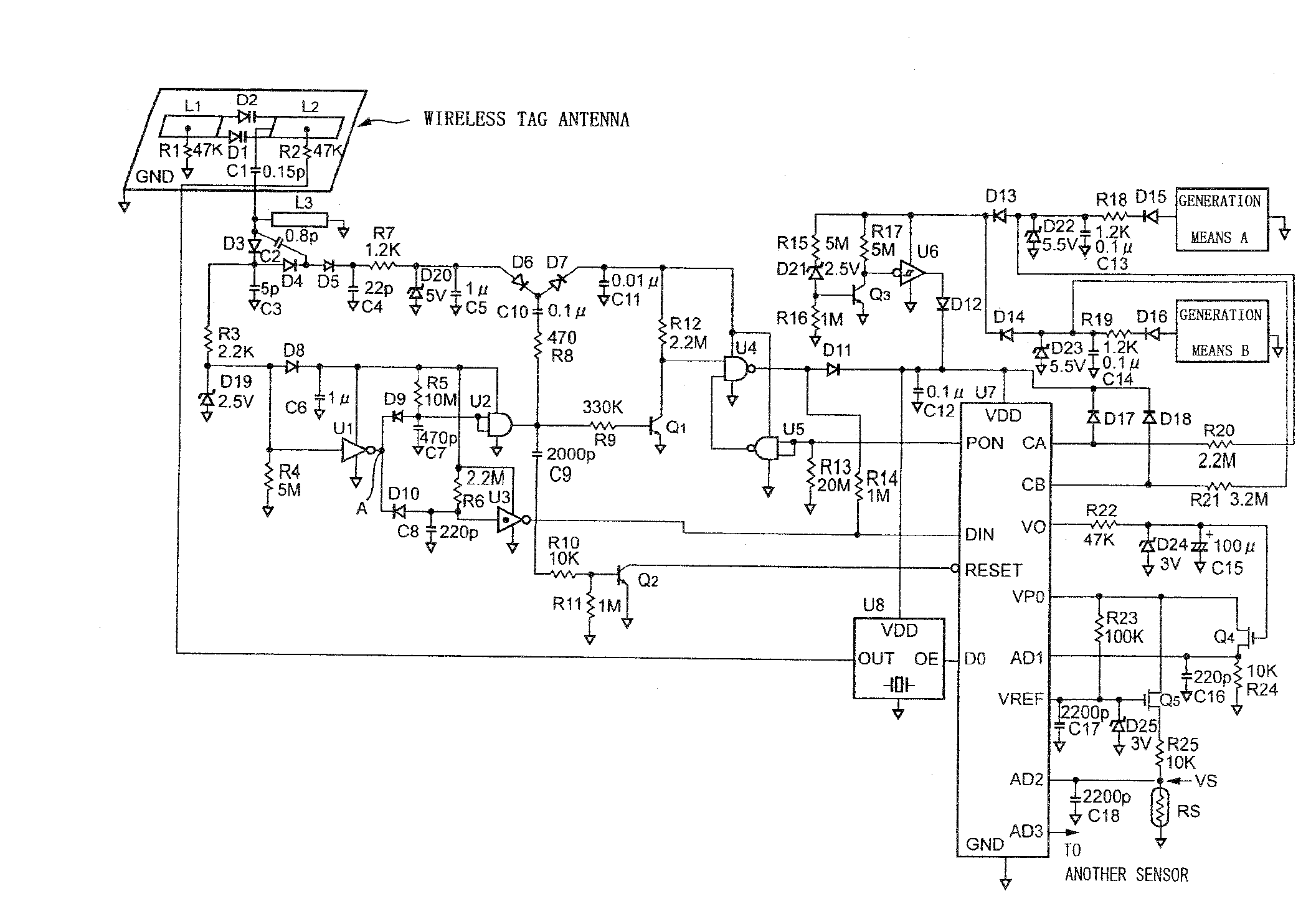
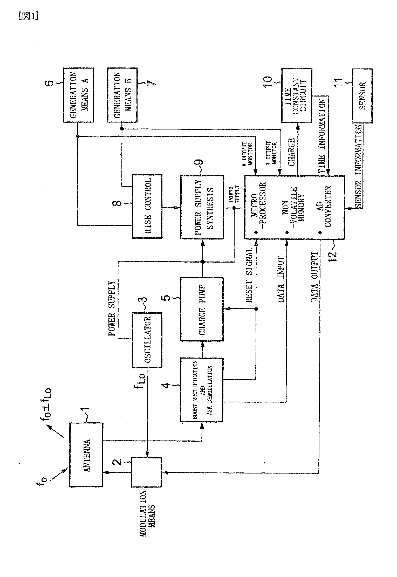
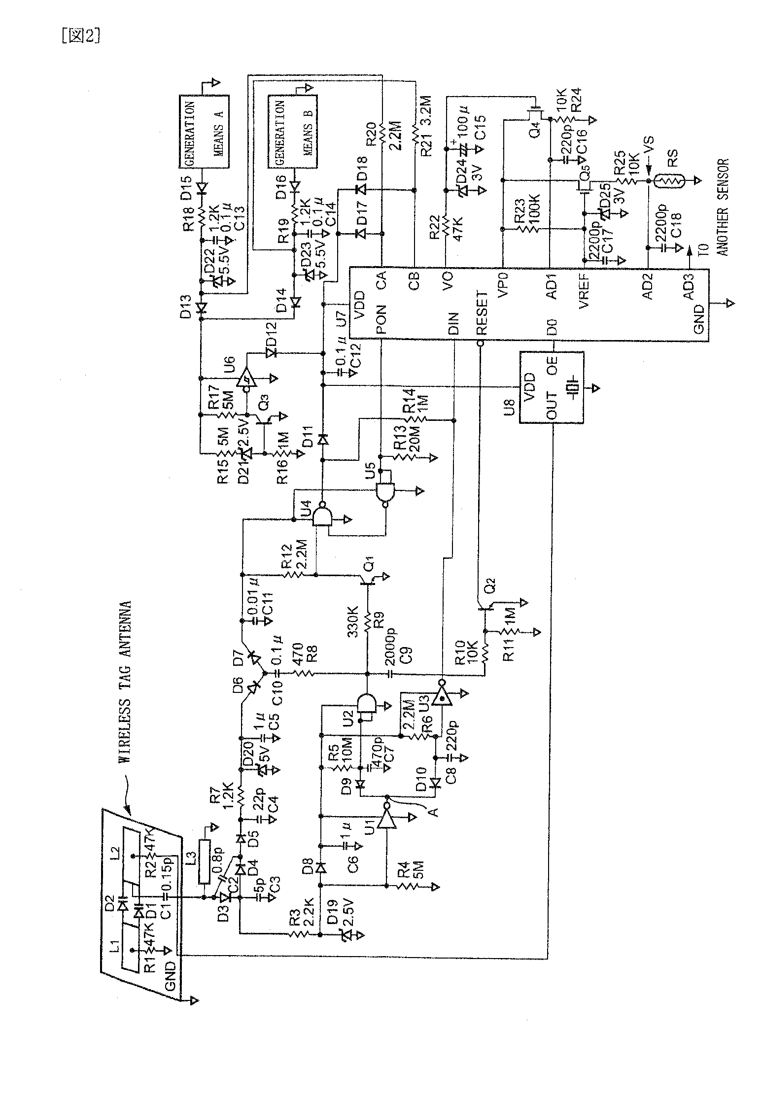
[0091]FIG. 1 shows a block diagram of a passive type sensor tag device according to an embodiment of the present invention.

[0092]In FIG. 1, reference numeral 1 denotes an antenna (divided microstrip antenna); 2, modulation means; 3, an oscillator; 4, a composite circuit including a boost rectification circuit and an ASK demodulation circuit; 5, a charge pump; 6, generation means (A); 7, generation means (B); 8, a rise control circuit; 9, a power supply synthesis circuit; 10, a time constant circuit; 11, a sensor; and 12, a control circuit (having a built-in microprocessor / non-volatile memory / AD converter).

[0093]The sensor tag device according to this embodiment has the following characteristics.

(1) A part of a boost rectification circuit (see Japanese Patent Application Laid-open No. 2004-304876) called a Cockcroft-Walton circuit in which a plurality of rectifier diodes and a plurality of capacitor are ladder-connected is utilized to provide ASK demodulation means.

(2) An output sign...


PUM


Abstract

There is provided a sensor tag device capable of detecting event data by a sensor tag all the time even when no radio wave is received, saving power supply for a microprocessor, and enlarging the radio communication distance. The sensor tag device includes generation means 6 and 7 using one or more environmental changes, power supply voltage rise control means 8, and power supply synthesis means 9, and power is supplied to a microprocessor 12 and event data is stored in the microprocessor 12 when an event, i.e., an environmental change has occurred. A power receiving circuit having a transmission/reception antenna, a built-in power receiving circuit, and the microprocessor and capable of bi-directional communication by radio waves is combined with a stab resonance RF boost circuit and a ladder boost rectification circuit.

Description

TECHNICAL FIELD[0001]The present invention relates to a sensor tag, and more particularly to a sensor tag device which is used in, e.g., a passive type wireless tag device with a sensor having no battery, and stores an event occurrence factor, sensor data (e.g., event detection data), and event information, e.g., an event occurrence time in an internal nonvolatile memory when, e.g., an event occurs, and wirelessly sends back the stored information with respect to an inquiry wirelessly supplied from an inquirer.BACKGROUND ART[0002]Patent Document 1: Japanese Patent Application Laid open No. 2000-258254 “Temperature Recording Device”[0003]There is a sensor tag device as a device, which is disposed to an article or a container to measure information of a time that varies every second at regular time intervals and from which a temperature history can be read at a later stage by utilizing a wireless communication line.[0004]This sensor tag device can be disposed to many kinds of objects ...

Claims


Application Information

Patent Timeline
Patent Type & Authority Applications(United States)
IPC IPC(8): H04Q5/22G06K19/07H01Q13/08H04B1/59H04B5/02
CPCG06K19/0713H01Q1/2225Y02B60/50H04B5/0043H04B5/02H01Q13/08Y02D30/70
Inventor KITAYOSHI, HITOSHISAWAYA, KUNIO
Owner KITAYOSHI HITOSHI
Why Eureka
Try Eureka