
Elevator linear motor drive

a linear motor and drive shaft technology, applied in the direction of packaging bottles, transportation and packaging, packaging goods types, etc., can solve the problems of large footprint of the machine for processing substrates, large space requirements, and complex process of substrate processing, etc., to improve the movement of the substrate carrier, fast and secure

Inactive Publication Date: 2009-05-14
INTEVAC
View PDF10 Cites 0 Cited by
  • Summary
  • Abstract
  • Description
  • Claims
  • Application Information

AI Technical Summary

Benefits of technology

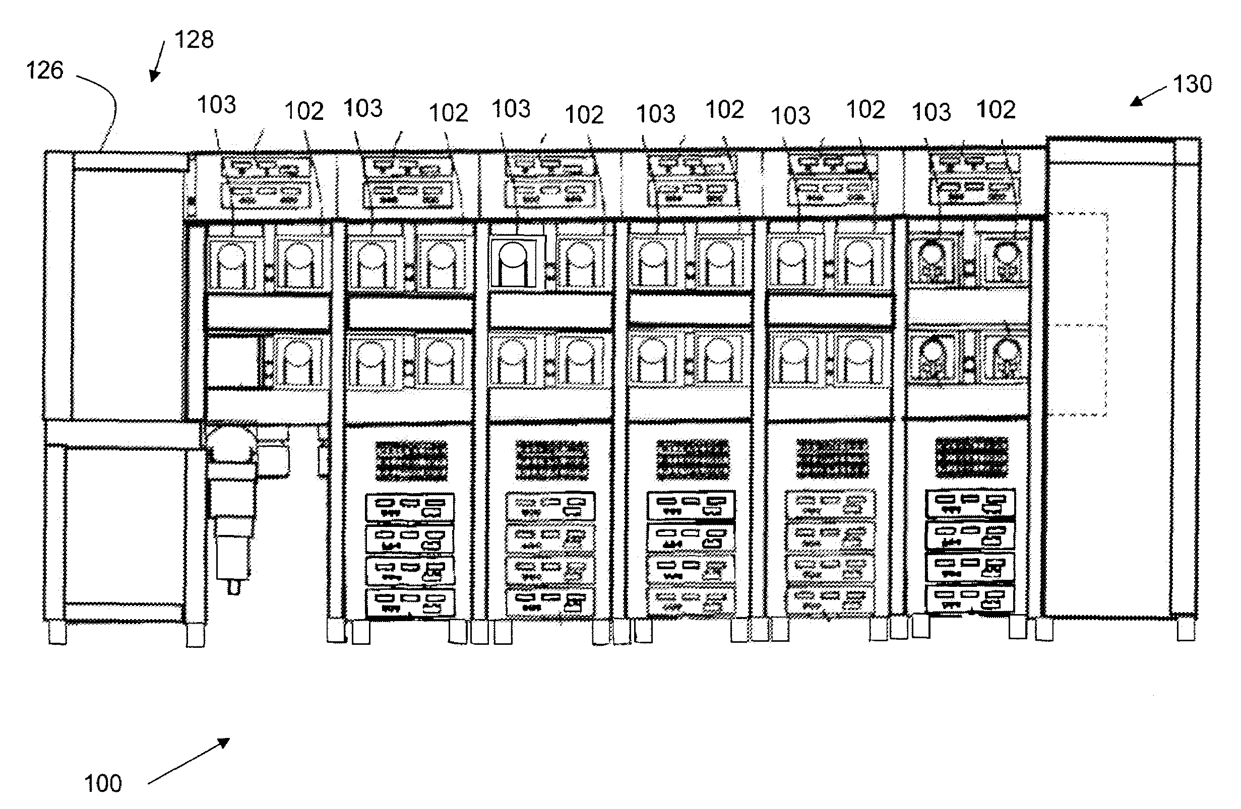
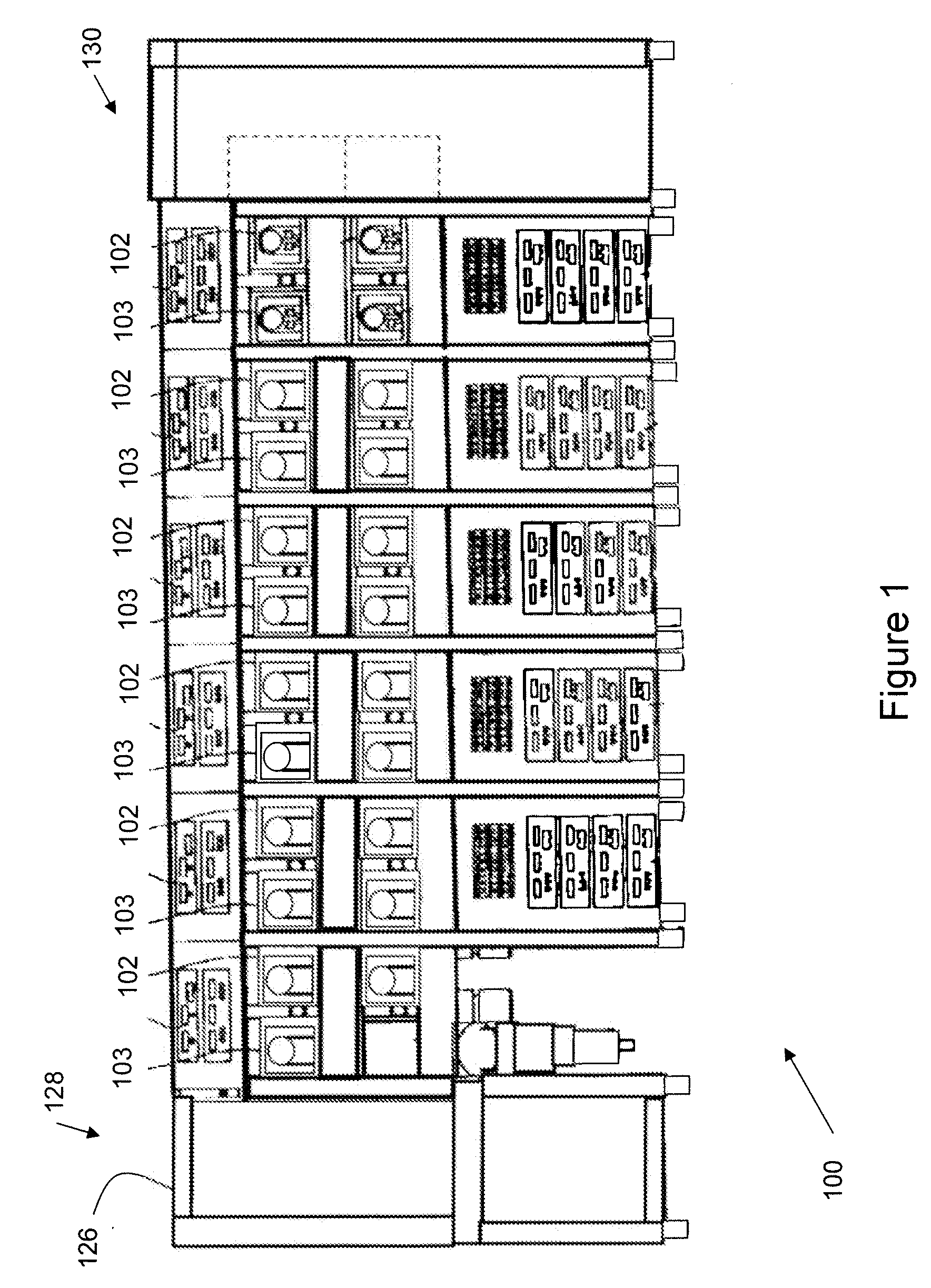
[0009]Embodiments of the present invention provide for a substrate processing system with a magnetic conduit configuration to improve the movement of a substrate carrier within the system. In one aspect, the configuration of magnetic conduits specifically provides for fast, secure movement of a carrier in an elevator subsystem of the substrate processing system by using magnetic conduits to redirect magnetic forces created by a linear motor, permitting the linear motor to be positioned outside of the system and in a location that will not interfere with the movement of the elevator.
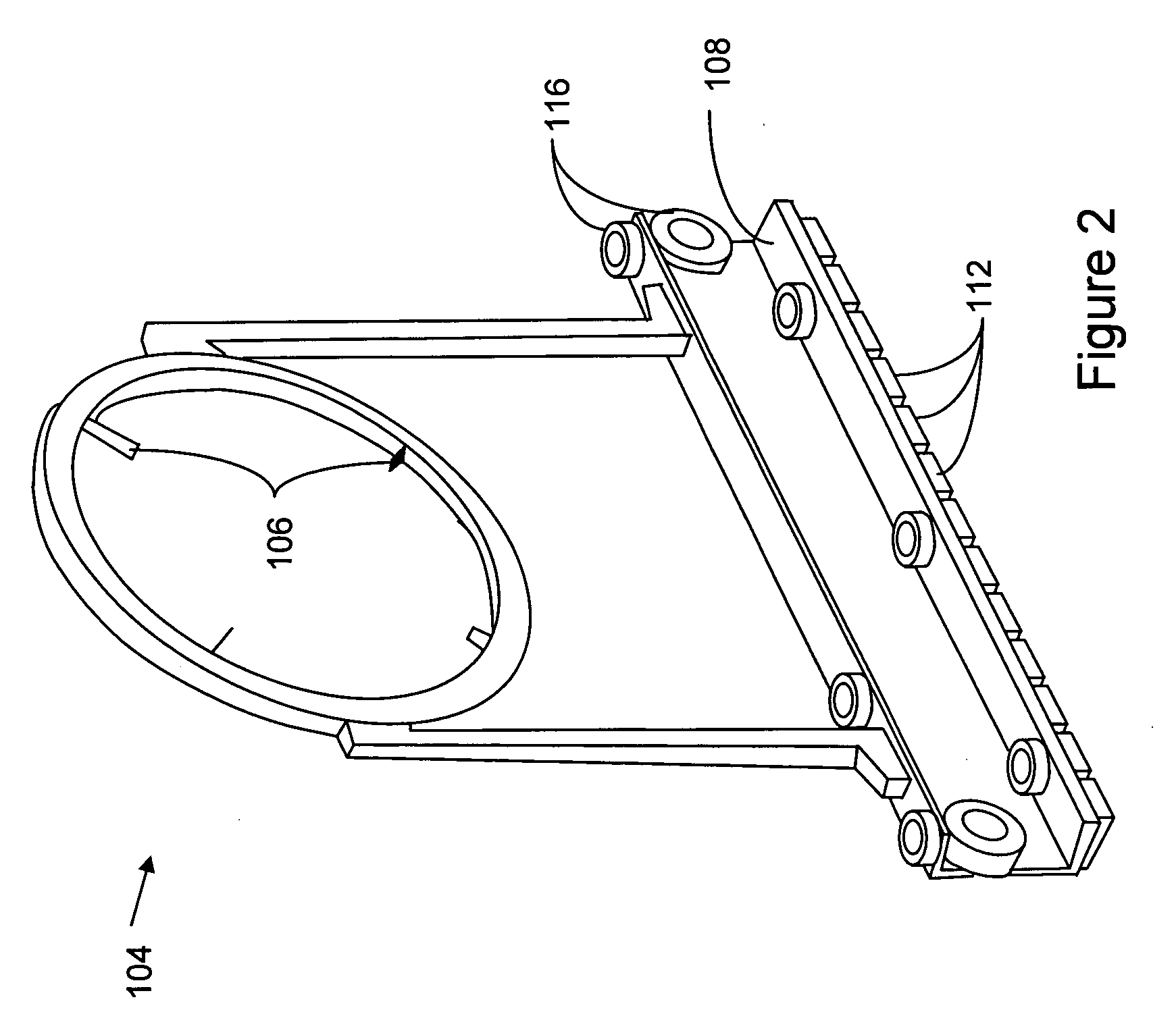
[0011]According to other aspects of the invention, an elevator subsystem in a substrate processing system is provided, comprising: an elevator chamber capable of sustaining a vacuum; at least one linear motor positioned outside the elevator chamber, wherein the linear motor generates a magnetic motive force; a movable carrier comprising a plurality of magnetic elements; a vertically-movable elevator base for moving the carrier vertically; and a plurality of pole pieces attached to the elevator base and coupling the magnetic field from the linear motor to the magnetic elements. The elevator subsystem may further comprise a series of adjacent pole pieces configured to decouple the carrier from a linear motor in an adjoining processing chamber and guide the carrier into the elevator chamber. The elevator subsystem may further comprise a series of rails attached to the elevator base to guide the carrier into the elevator chamber. The plurality of pole pieces may be positioned below the underside of the carrier so as to enhance the stability of the carrier by enhancing the gravitational forces on the carrier. The pole pieces may be formed in an “L” shape, such that the linear motor is located on a lateral wall of the elevator chamber while the carrier is coupled to the pole pieces on its underside. The wall of the elevator chamber between the linear motor and the plurality of pole pieces may be a thin metallic material. The wall may be aluminum. The pole pieces may be made of a permeable, soft metal to minimize the magnetic field loss between the linear motor and the pole pieces. The pole pieces may be a 400 series stainless steel or iron. Each of the magnetic elements may comprise a magnet attached to a metallic block.

Problems solved by technology

Substrate processing, such as the formation of magnetic disks, is a complex and complicated process.
Machines for processing substrates usually have a large footprint, and require a significant amount of space to operate.
Additionally, the machines need to be operated in high-tech clean rooms, which are expensive to build and maintain.
Improving the processing speed is somewhat challenging, since many processing steps have a minimum required time that a particular coating must be applied, heated, or cooled in order to properly coat a substrate.
As a result, the carrier has a somewhat flimsy hold on the substrate.
A slight bump to the carrier from any direction could knock the substrate out of the carrier, requiring the entire machine to be stopped and serviced.

Method used


Image

  • Elevator linear motor drive
  • Elevator linear motor drive
  • Elevator linear motor drive

Examples


Embodiment Construction

[0024]Before the present invention is described, it is to be understood that this invention is not limited to particular embodiments described, as such may, of course, vary. It is also to be understood that the terminology used herein is for the purpose of describing particular embodiments only, and is not intended to be limiting, since the scope of the present invention will be limited only by the appended claims.

[0025]Aspects of the present invention provide for the use of magnetic conduits to improve the time required to move a substrate and carrier from one level to another on a stacked, multi-level substrate processing system. Less mechanical parts are required to move the carrier into an elevator subsystem, and only minimal, shear magnetic forces must be broken when moving the carrier from an adjoining processing chamber to an elevator chamber. Additionally, the use of the magnetic conduits, especially configured in adjacent arrangements of pole pieces, can stabilize the movem...


PUM


Abstract

Disclosed is a substrate processing system with a magnetic conduit configuration to improve the movement of a substrate carrier within the system. The configuration specifically provides for safe, secure movement of a carrier between multiple levels of a substrate processing system by using magnetic conduits to redirect magnetic forces created by a linear motor, permitting the linear motor to be positioned outside of the system and in a location that will not interfere with the movement of the carrier.

Description

FIELD OF THE INVENTION[0001]This invention relates to a system and method for handling and processing substrates such as magnetic disks, and more specifically to a system and method for improved movement of a substrate carrier in a substrate processing system using magnetic conduits.BACKGROUND OF THE INVENTION[0002]Substrate processing, such as the formation of magnetic disks, is a complex and complicated process. Large, customized equipment is required to carry out the numerous unique steps of coating a substrate with multiple layers, then heating and cooling the substrate. Machines for processing substrates usually have a large footprint, and require a significant amount of space to operate. Additionally, the machines need to be operated in high-tech clean rooms, which are expensive to build and maintain. Therefore, it is advantageous to reduce the overall footprint of the substrate processing machines.[0003]It is also desired to improve the processing speed at which each substrat...

Claims


Application Information

Patent Timeline
Patent Type & Authority Applications(United States)
IPC IPC(8): H01L21/677B65G65/30
CPCH01L21/67346H01L21/67748G11B5/8404H01L21/67751H01L21/67742Y10S414/139H01L21/67709H01L2221/67H01L21/68
Inventor SCOLLAY, STUART
Owner INTEVAC
Learn More