Automatic gain control circuit

a gain control circuit and gain control technology, applied in the direction of electrical equipment, radio transmission, transmission, etc., can solve the problems of reducing the sensitivity of the receiving station, particularly the distortion characteristic of the signal, and reducing the level of the signal to be input to the second radio frequency amplifying circuit, so as to reduce the level of the received signal and facilitate the distortion

Inactive Publication Date: 2009-05-14
NSC CO LTD
View PDF1 Cites 41 Cited by
  • Summary
  • Abstract
  • Description
  • Claims
  • Application Information

AI Technical Summary

Benefits of technology

[0015]The AGC circuit shown in FIG. 5 is effective for reducing a level of a disturbing wave included in a received signal. For example, when a strong disturbing wave enters, a gain of the received signal is reduced so that a signal level of the disturbing wave can be decreased. However, the received signal to be a target for reducing a gain includes a signal having a desirable frequency in addition to the signal of the disturbing wave which makes a noise. Accordingly, if the AGC circuit is operated when the signal having the desirable frequency has a low level, the level of the signal having the desirable frequency which is originally low is reduced still more. As a result, there is a problem in that a suppression in a sensitivity is caused, for example, a receiving sensitivity of a desirable station is remarkably reduced.
[0020]In general, the greater the level of the received signal, the easier a distortion occurs in the signal if the level is simply amplified by the radio frequency amplifying circuit. On the other hand, according to the present invention, when the level of the received signal is higher than the predetermined threshold, it is attenuated by the variable attenuating circuit and is then amplified by the necessary quantity through the second radio frequency amplifying circuit. Therefore, the level of the signal to be input to the second radio frequency amplifying circuit is comparatively reduced. Even if the signal is amplified, the distortion of the signal occurs with difficulty. consequently, in the case in which the AGC starting level is increased to inhibit the suppression in a sensitivity, it is possible to suppress a deterioration in the distortion characteristic when a received signal having a high level is input. Thus, it is possible to cause an improvement in the suppression in a sensitivity and an improvement in the distortion characteristic to be compatible with each other.

Problems solved by technology

As a result, there is a problem in that a suppression in a sensitivity is caused, for example, a receiving sensitivity of a desirable station is remarkably reduced.
For this reason, a distortion characteristic of the signal, particularly, an intermodulation distortion characteristic is deteriorated.
In other words, there is a problem in that the suppression in a sensitivity is caused when the AGC starting level is reduced, and the distortion characteristic is deteriorated when the AGC starting level is increased.

Method used


Image

  • Automatic gain control circuit
  • Automatic gain control circuit
  • Automatic gain control circuit

Examples


first embodiment

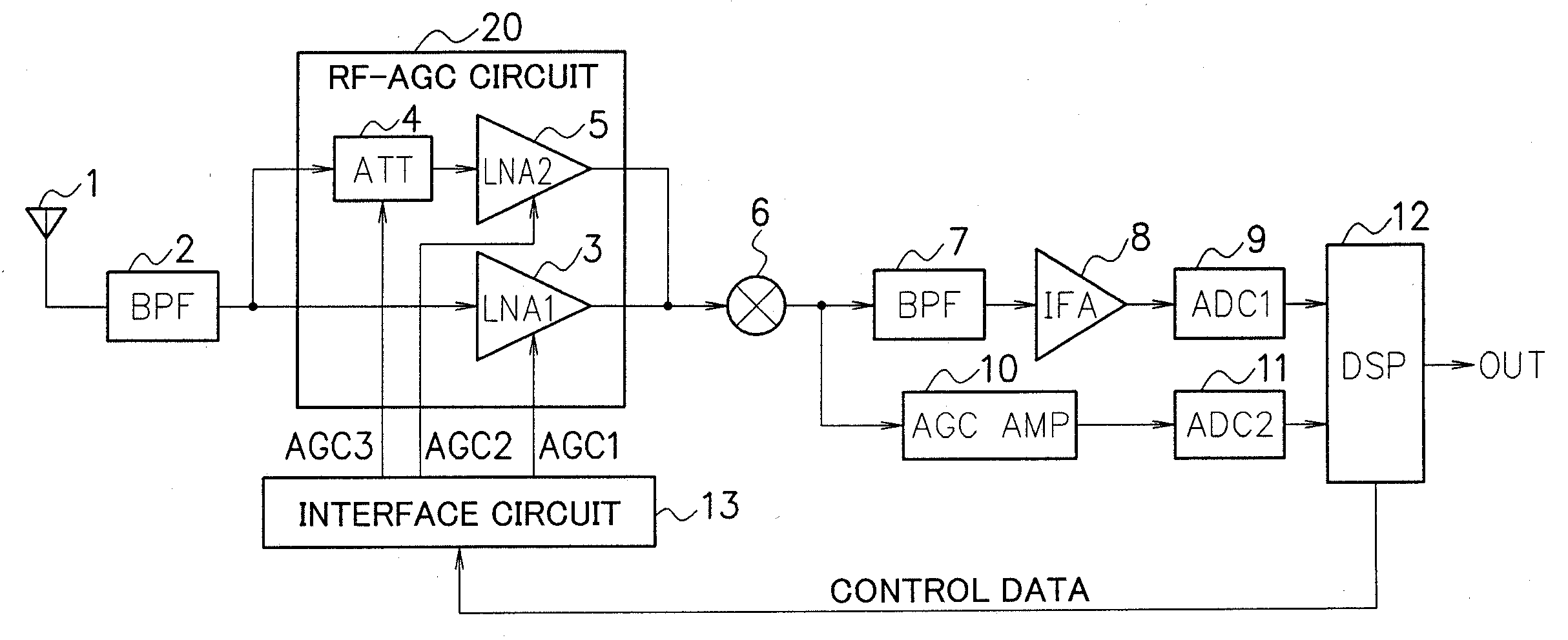
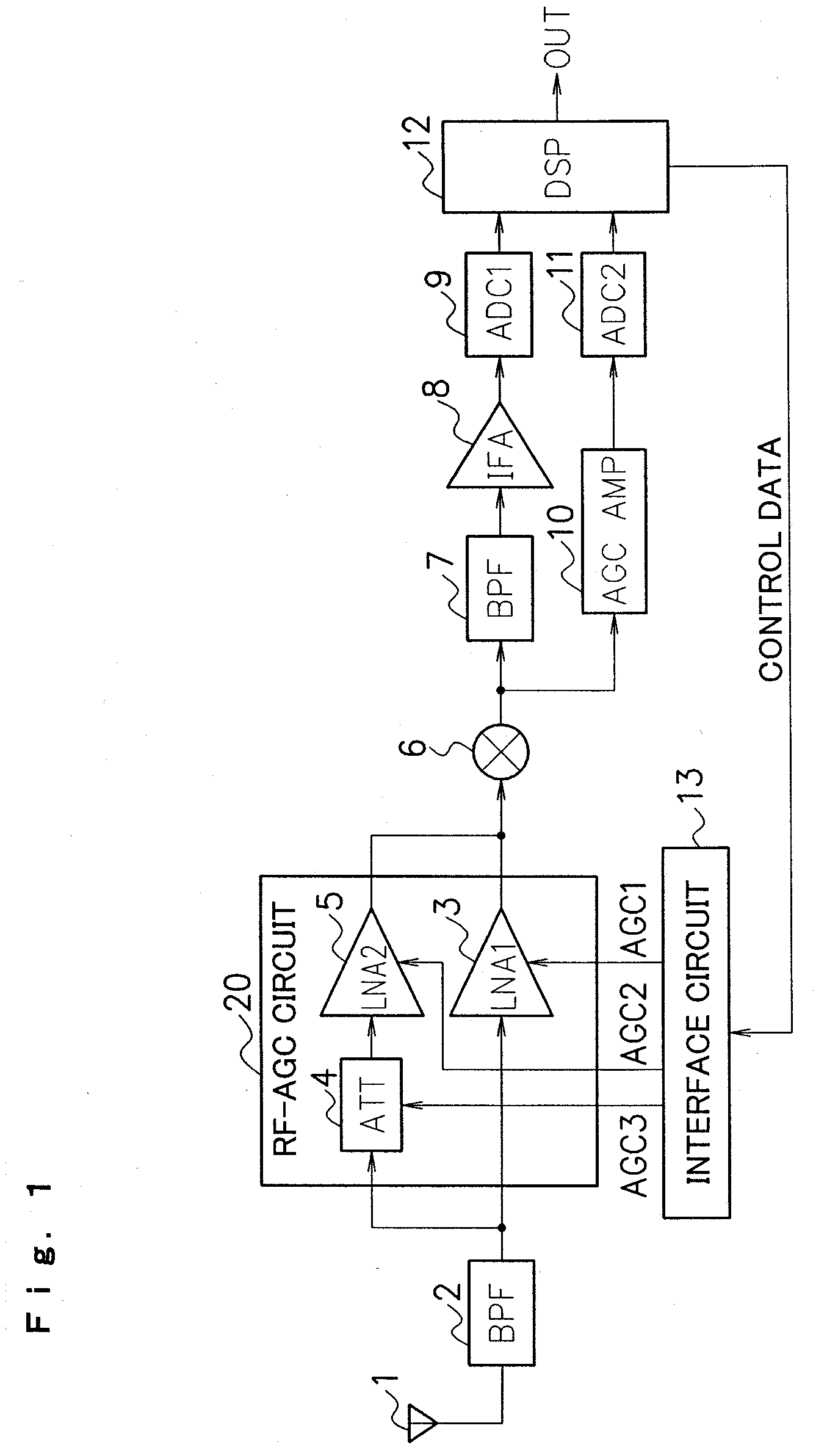
[0027]An embodiment according to the present invention will be described below with reference to the drawings. FIG. 1 is a diagram showing an example of a whole structure of an automatic gain control circuit (an RF-AGC circuit 20) and a radio receiver applying the RF-AGC circuit 20 according to a first embodiment.

[0028]As shown in FIG. 1, the radio receiver according to the present embodiment is constituted by an antenna 1, a band-pass filter (BPF) 2, a first LNA 3, an antenna damping circuit 4, a second LNA 5, a frequency converting circuit 6, a BPF 7, an IF amplifier 8, a first A / D converting circuit 9, an AGC amplifier 10, a second A / D converting circuit 11, a DSP (Digital Signal Processor) 12, and an interface circuit 13. These structures (excluding the antenna 1) are integrated into a single semiconductor chip through a CMOS (Complementary Metal Oxide Semiconductor) process, for example.

[0029]The BPF 2 selectively outputs a broadcast wave signal of a specific frequency band fro...

second embodiment

[0053]Next, a second embodiment according to the present invention will be described with reference to the drawings. FIG. 3 is a diagram showing an example of a structure of an RF-AGC circuit 30 according to the second embodiment. The RF-AGC circuit 30 is used in place of the RF-AGC circuit 20 in the radio receiver shown in FIG. 1.

[0054]As shown in FIG. 3, the RF-AGC circuit 30 according to the second embodiment includes a fixed attenuating circuit 14 in addition to a first LNA 3, an antenna damping circuit 4 and a second LNA 5. The fixed attenuating circuit 14 attenuates a radio frequency signal passing through a BPF 2 by a fixed quantity of an attenuation and is connected to an input stage of the first LNA 3 (between the BPF 2 and the first LNA 3). More specifically, a first signal path is constituted by the fixed attenuating circuit 14 and the first LNA 3.

[0055]The fixed attenuating circuit 14 is constituted by a capacitor C and a switch SW which are connected in series between a...

third embodiment

[0057]Next, a third embodiment according to the present invention will be described with reference to the drawings. FIG. 4 is a diagram showing an example of a structure of an RF-AGC circuit 40 according to the third embodiment. The RF-AGC circuit 40 is used in place of the RF-AGC circuit 20 in the radio receiver shown in FIG. 1.

[0058]As shown in FIG. 4, the RF-AGC circuit 40 according to the third embodiment includes a second antenna damping circuit 15 and a bypass switch 16 in addition to a first LNA 3, an antenna damping circuit 4 and a second LNA 5. The second antenna damping circuit 15 corresponds to a second variable attenuating circuit according to the present invention and controls a radio frequency signal passing through a BPF 2 to have a degree of an attenuation which is variably set based on a fifth AGC signal. The bypass switch 16 is connected in series to the second antenna damping circuit 15 and is turned ON / OFF in response to a sixth AGC control signal supplied from a...


PUM


Abstract

A first signal path including a first LNA 3 and a second signal path including an antenna damping circuit 4 and a second LNA 5 are connected in parallel, and switching into either the first signal path or the second signal path is carried out to control a gain of a received signal. When a level of the received signal is higher than a first threshold, it is once attenuated by the antenna damping circuit 4 and is then amplified by a necessary quantity through the second LNA 5. Thus, the gain of the received signal is controlled in a total of the attenuation and the amplification. Consequently, a level of a signal to be input to the second LNA 5 is reduced to cause a distortion of the signal in the amplification with difficulty.

Description

FIELD OF THE INVENTION[0001]The present invention relates to an automatic gain control circuit, and more particularly to an automatic gain control circuit including a radio frequency amplifier and an attenuator which have variable gains and carrying out an AGC operation for suppressing a distortion of a signal when a signal having a high level is input to a wireless communicating apparatus such as a radio receiver.DESCRIPTION OF THE RELATED ART[0002]A wireless communicating apparatus such as a radio receiver is usually provided with an AGC (Automatic Gain Control) circuit for controlling a gain of a received signal. An RF (Radio Frequency)-AGC circuit controls a gain of a radio frequency signal (an RF signal) received by an antenna and maintains a level of the received signal to be constant. The RF-AGC can be implemented by controlling a quantity of an attenuation of a signal level in an antenna damping circuit or a quantity of an amplification of the signal level in an LNA (Low Noi...

Claims


Application Information

Patent Timeline
Patent Type & Authority Applications(United States)
IPC IPC(8): H04B1/06
CPCH04B1/18
Inventor ISHIGURO, KAZUHISA
Owner NSC CO LTD
Why Eureka
Try Eureka