Spinal implant having a post-operative adjustable dimension

Active Publication Date: 2009-05-14
SPINE21 LTD
View PDF48 Cites 352 Cited by
  • Summary
  • Abstract
  • Description
  • Claims
  • Application Information

AI Technical Summary

Benefits of technology

[0011]In accordance with an embodiment of the present invention the post-implantation variabl

Problems solved by technology

Unfortunately, fusion tends to have significant shortcoming and may cause the problem to migrate to adjacent vertebral components.
Ho

Method used


Image

  • Spinal implant having a post-operative adjustable dimension
  • Spinal implant having a post-operative adjustable dimension
  • Spinal implant having a post-operative adjustable dimension

Examples


Embodiment Construction

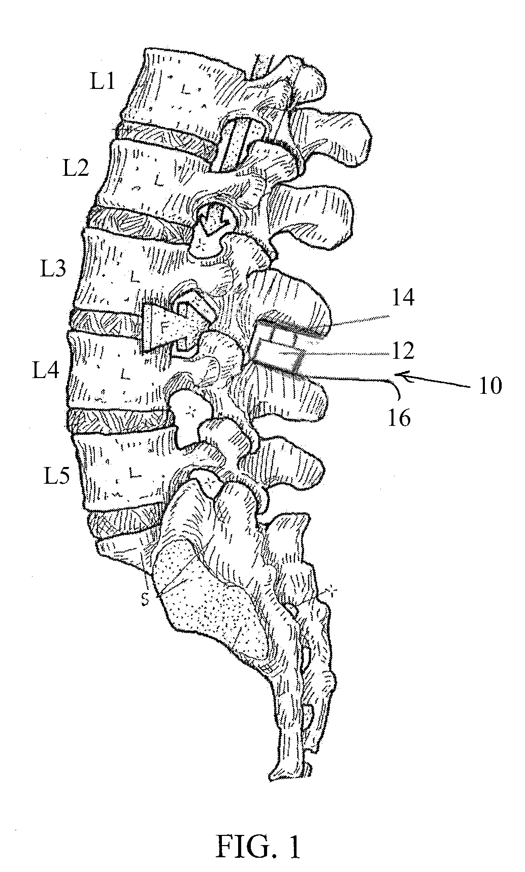
[0031]Reference is now made to FIG. 1, which illustrates a spinal implant 10, constructed and operative in accordance with an embodiment of the invention.

[0032]Spinal implant 10 is shown implanted between two adjacent spinous processes of the lumbar spine (in this example, spinal implant 10 is an interspinous process device). Spinal implant 10 includes a post-implantation variable dimension device 12 disposed between a first (upper) support end plate (spinal attachment member) 14 and a second (lower) support end plate (spinal attachment member) 16. The post-implantation variable dimension device 12 may include a post arranged for linear motion (slightly tilted from vertical in the sense of the drawing), such as by means of a miniature linear actuator which is remote controlled. In general, post-implantation variable dimension device 12 may be constructed in accordance with any of the embodiments described below with reference to FIGS. 6-9.

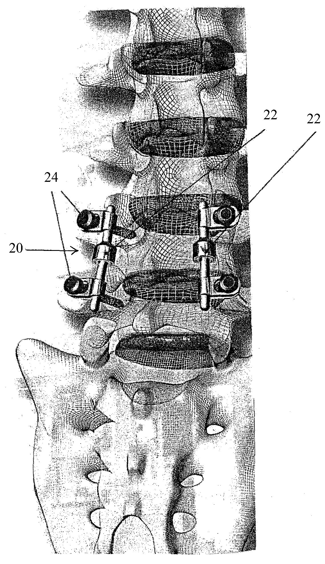
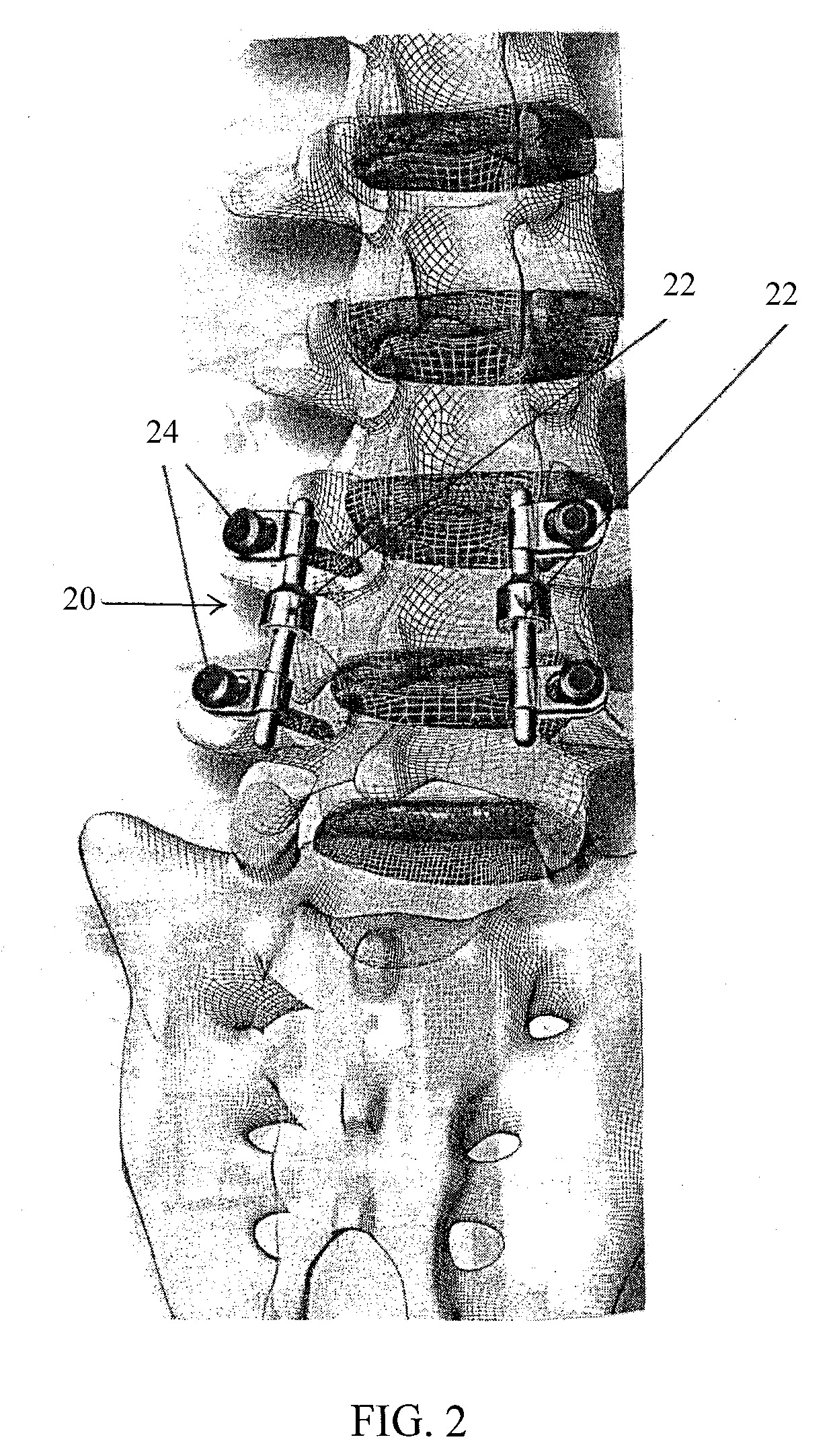
[0033]Reference is now made to FIG. 2, which...


PUM

PropertyMeasurementUnit
Dimensionaaaaaaaaaa
Distanceaaaaaaaaaa

Abstract

A spinal implant including first spinal attachment member for attaching to a first spinal portion, second spinal attachment member for attaching to a second spinal portion, and a post-implantation variable dimension device disposed between the first and second spinal attachment members, which is operable after completing surgery in which said spinal implant was installed into a patient, to cause relative movement between the first and second spinal attachment members.

Description

FIELD OF THE INVENTION[0001]The present invention relates generally to spinal implants and prostheses, and particularly to a spinal implant having a post-operative adjustable dimension.BACKGROUND OF THE INVENTION[0002]Spinal stenosis, as well as spondylosis, spondylolisthesis, osteoarthritis, scoliosis and other degenerative phenomena may be the cause of back pain, and may be caused by a narrowing of the spinal canal or foramina that result in stress acting on the spinal cord and / or nerve roots.[0003]One of the methods for resolving back pain involves decompression, the removal of bony elements causing the pain, and fusion of two or more adjacent vertebrae. Unfortunately, fusion tends to have significant shortcoming and may cause the problem to migrate to adjacent vertebral components. Among the non-fusion solutions are disc replacement, dynamic stabilization systems and inter-spinous process implants.[0004]Spinal implants with the capability of height adjustment are known. For exam...

Claims


Application Information

Patent Timeline
IPC IPC(8): A61B17/58A61F2/44A61B17/56
CPCA61B17/025A61F2250/0009A61B17/7014A61B17/7016A61B17/7017A61B17/7062A61B2017/00022A61B2017/00212A61B2017/00221A61B2017/00539A61B2017/00544A61B2017/00557A61B2017/00734A61B2017/0256A61F2/441A61F2/4455A61F2002/30471A61F2002/30507A61F2002/30525A61F2002/30527A61F2002/3055A61F2002/30553A61F2002/30556A61F2002/30601A61F2002/30668A61F2002/482A61F2002/485A61F2220/0025A61F2220/0091A61F2250/0001A61F2250/0008A61B17/70A61F2002/30523A61F2/482A61F2/484
Inventor ARNIN, URI
Owner SPINE21 LTD
Why Eureka
Try Eureka