Systems and methods for diagnosing production problems in oil field operations

a technology for oil field operations and production problems, applied in the direction of instruments, navigation instruments, nuclear elements, etc., can solve the problems of no integrated, ready-to-use processes to assist department managers, increasing complexity of oil field operations, and no end in sigh

Inactive Publication Date: 2009-05-14
CHEVROU USA INC
View PDF41 Cites 41 Cited by
  • Summary
  • Abstract
  • Description
  • Claims
  • Application Information

AI Technical Summary

Benefits of technology

[0018]The map and objects are generated by a master schedule visualizer system. The system includes the plurality of incompatible software applications, each having a different domain-specific functionality useful for oil field management and having a work crew scheduling code segment, each in communication with a dedicated database, each software application loaded into memory of a general purpose personal computer or general purpose server class computer. The system also includes a middle-ware software code segment layer in communication with each of the domain-specific software applications for extracting work schedule data from each of the domain-specific software applications. The system further includes a geographic information system in communication with the middle-ware software code segment layer for displaying an oil field map, oil well objects, oil field facility objects, surface and sub-surface work crew objects, and safety zones objects. The system also includes a plurality of input devices operatively connected with the middle-ware software code segment layer for allowing a plurality of users to input instructions to the middle-ware software code segment layer and communicate with the software applications. The first and one or more video monitors are operatively connected with the middle-ware software code segment layer and the geographic information system, for displaying the oil field map, oil well objects, oil field facility objects, surface and sub-surface work crew objects, and safety zones objects, and reports from the domain-specific software applications.

Problems solved by technology

The complexity of oil field operations continues to increase with no end in sight.
Each department in oil field operations (for example: production, maintenance and engineering) further increases the complexity due to the fact that each department has its own methodology and specialized tools to achieve their individual goals.
There are no integrated, ready-to-use processes to assist department managers in setting up an infrastructure to facilitate an integrated communication between different departments.
In addition, these different tools are typically not compatible with each other so that it is difficult to share information between the different tools.
Thus, an operations manager may find it difficult to visualize the whole picture since there is no single tool for viewing the information generated by all of the various tools.
As a result, department managers spend a lot of their working time in meetings or on the phone exchanging information, such as scheduling information and the like.
In general, the time spent on collaboration increases directly with the complexity of the work that needs to be done.
The problem with typical collaboration methods is that they tend to be error-prone, inefficient, temporary, expensive and very risky.
Perhaps the most dangerous situation a company can face in the producing field is one where simultaneous operations are involved, especially where drilling, production, and construction crews are all working on the same site.
If maintenance work is being performed on a certain piece of equipment without all affected departments being advised, serious safety issues could arise in the field for work crews having incorrect information.
This obviously can lead to disastrous consequences.

Method used


Image

  • Systems and methods for diagnosing production problems in oil field operations
  • Systems and methods for diagnosing production problems in oil field operations
  • Systems and methods for diagnosing production problems in oil field operations

Examples


Embodiment Construction

[0027]So that the above recited features and advantages of the present invention can be understood in detail, a more particular description of the invention, briefly summarized above, may be had by reference to the embodiments thereof that are illustrated in the appended drawings. It is to be noted, however, that the appended drawings illustrate only typical embodiments of this invention and are therefore not to be considered limiting of its scope, for the invention may admit to other equally effective embodiments.

[0028]Embodiments describing the components and method of the present invention are referenced in FIGS. 1 to 8. More specifically, the following embodiments describe the architecture, workspaces and example use cases of a master schedule visualizer 100, for implementing the present invention.

A. System Architecture and Elements of One Embodiment

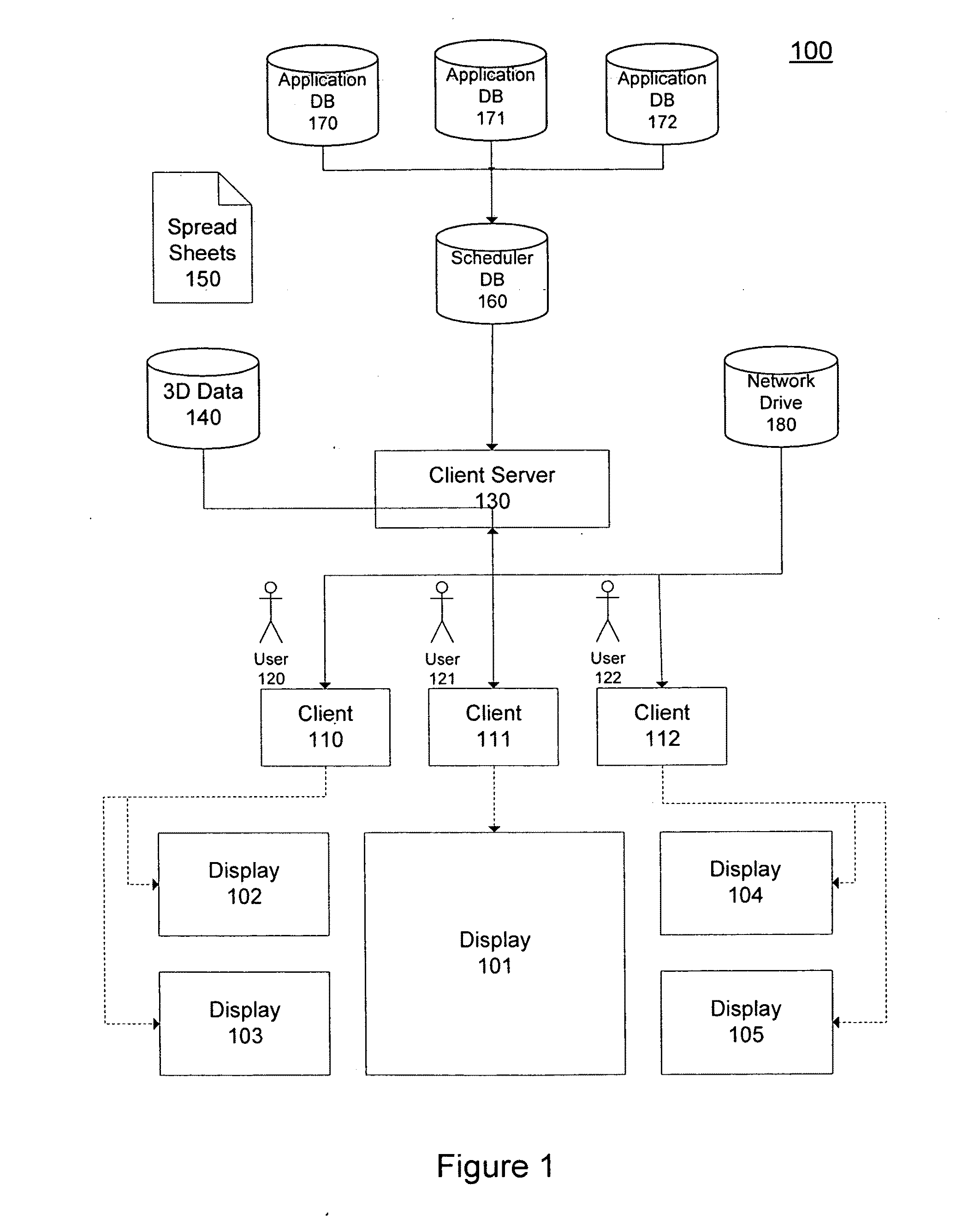
[0029]FIG. 1 is a schematic diagram depicting in one embodiment the system architecture of the master schedule visualizer of the in...


PUM


Abstract

Systems and methods for diagnosing production problems in oil field operations are provided. A first video monitor displays an oil field diagnosis process flow chart that includes selectable objects such as Review Well Test Differences, Review Sliders, Review Bad Actors, and Perform Steam Flood Performance Check. Each selectable object is associated with one or more incompatible domain-specific software applications. One or more of the selectable objects are selected and one or more additional video monitors display reports extracted by a middle-ware software code segment layer from the associated domain-specific software applications. Oil wells having production problems are listed and problem oil wells are displayed on an oil field map. Any commonalities among the displayed problem oil wells indicative of a common cause of the production problems are visually identified. Work is scheduled in the associated domain-specific software applications sufficient to remedy the common cause.

Description

CROSS-REFERENCE TO RELATED APPLICATIONS[0001]The present application claims priority under 35 U.S.C. § 119 to U.S. Provisional Application Nos. 60 / 950,505 and 60 / 950,533 filed on Jul. 18, 2007, the entire disclosures of which are herein expressly incorporated by reference. The present application is also related to U.S. patent application Ser. No. ______, entitled “Systems and Methods for Managing Large Oil Field Operations”, filed on even date herewith (Attorney Docket No. T-7476) and U.S. patent application Ser. No. ______, entitled “Systems and Methods for Increasing Safety and Efficiency in Oil Field Operations”, filed on even date herewith (Attorney Docket No. T-6791), the entire disclosures of which are herein expressly incorporated by reference.FIELD OF THE INVENTION[0002]The present invention relates to a method for increasing safety and efficiency in oil field operations, diagnosing production problems in oil field operations and managing large oil field operations.BACKGROU...

Claims


Application Information

Patent Timeline
Patent Type & Authority Applications(United States)
IPC IPC(8): G06Q10/00G06F15/00G06Q50/00G01C21/00
CPCG06Q10/06G06Q50/02G06Q10/06395Y02P90/80Y02A10/40
Inventor BRINK, JAMESTUBBS, DALLASORAN, KENANOUIMETTE, JAMES RICHARD
Owner CHEVROU USA INC
Why Eureka
Try Eureka