
Trace data timestamping

a trace data and timestamp technology, applied in the field of timestamping generated trace data, can solve the problem of expensive use of trace bandwidth

Active Publication Date: 2009-05-14
ARM LTD
View PDF12 Cites 38 Cited by
  • Summary
  • Abstract
  • Description
  • Claims
  • Application Information

AI Technical Summary

Benefits of technology

[0013]The present technique recognises that when generating trace data for a data processing apparatus, useful trace data may be produced in which only a subset of the traced activities of the data processing apparatus are associated with a timing indication, allowing subsequent analysis of the trace data to correlate in time these activities with one another. For clarity it is noted that a “strict” subset is intended here, i.e. there are also traced activities of the data processing apparatus for which no timing indication is produced. Thus, by causing a timing indication to be added to the stream of trace elements produced for only a subset of the activities of the data processing apparatus already being traced, a reduction in the bandwidth of trace data output is achieved, whilst retaining the timing indication in association with those activities of the data processing apparatus that will require associated timing information when later analysed.
[0017]The present invention allows the user to concentrate on particular activities of interest, for example the execution of a barrier instruction, the barrier instruction ensuring that the effects of instructions before the barrier instruction are perceived from outside the processing component executing it to occur before effects of instructions after said barrier instruction. In a multi-processor system, such instructions make useful synchronisation points to ensure that certain activities of respective processors occur in a predetermined order. Hazards such as read-before-write may be avoided in this way.
[0018]Typically, the monitored circuitry produces a stream of data elements representative of its activities, from which the stream of trace elements is generated. According to one embodiment of the present invention, the detection circuitry detects the occurrence of the predetermined subset of activities from observation of the stream of data elements. This means that the existing arrangement of known, data element generating monitored circuitry can be used in the data processing apparatus of this embodiment of the present invention to produce a stream of data elements, without the need for modification. According to an alternative embodiment of the present invention, the detection circuitry is associated with the monitored circuitry and the detection circuitry detects the occurrence of the predetermined subset of activities from observation of the monitored circuitry, then adding at least one data element to the stream of data elements in order to cause the timing indication to be added to the stream of trace elements. In this arrangement the detection circuitry can more directly monitor the activities of the monitored circuitry and the trace circuitry can simply add a timing indication to the stream of trace elements when that at least one data element is recognised in the stream of data elements.
[0020]In one embodiment of the present invention one of the one or more predetermined instructions is a barrier instruction, the barrier instruction ensuring that the effects of instructions before the barrier instruction are perceived from outside the processing unit executing said barrier instruction to occur before effects of instructions after said barrier instruction. In a data processing apparatus in which the order in which instructions are executed varies from the order in which those instructions are included in program code, a barrier instruction is a useful tool when including timing indications in trace data, to provide reliable observation points for the temporal activity of the data processing apparatus in the trace stream.

Problems solved by technology

For example, the inventors of the present invention realised that in a data processing system in which techniques such as pipelining, write buffering, caching, speculation and / or out-of-order execution have been introduced to improve performance, situations arise where the information included in the trace stream indicative of each elapsed clock cycle is not at accurate as expected, and can become misleading when studying or debugging the activities of the data processing system as a whole, and furthermore is an expensive use of trace bandwidth.

Method used


Image

  • Trace data timestamping
  • Trace data timestamping
  • Trace data timestamping

Examples


Embodiment Construction

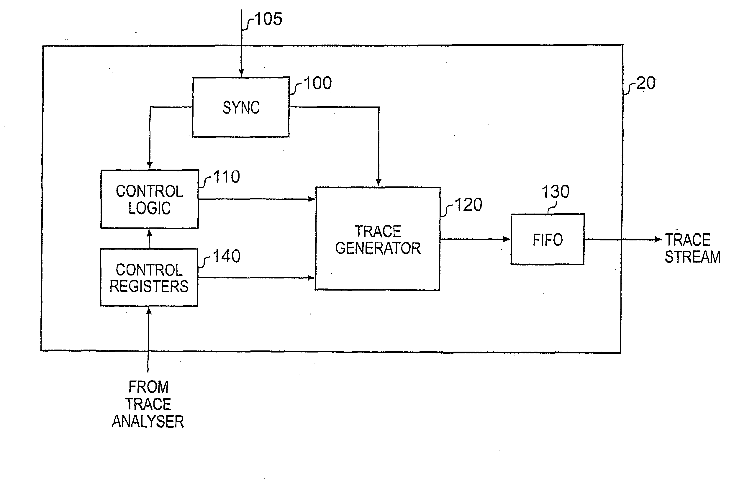
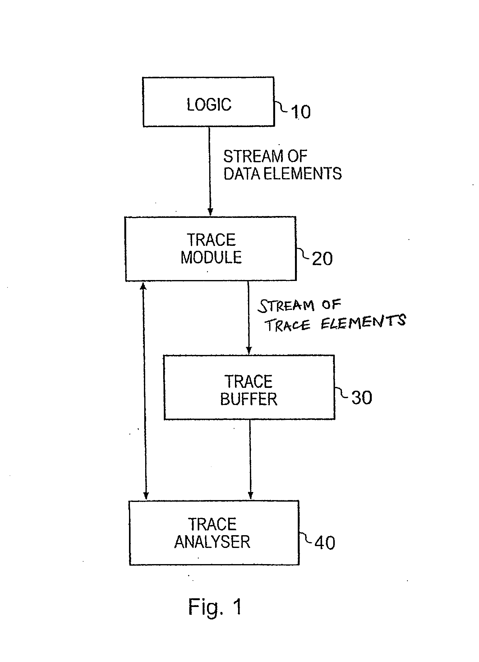
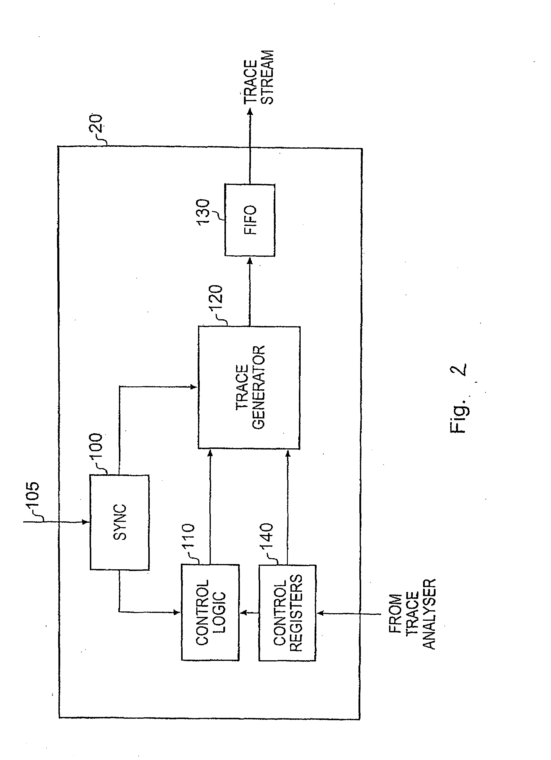
[0037]FIG. 1 schematically illustrates a data processing system providing logic 10, a trace module 20, a trace buffer 30 and a trace analyser 40. Whilst FIG. 1 illustrates a data processing system providing a trace buffer 30, in alternative embodiments the trace module 20 may pass its output straight to the trace analyser 40, without going via a trace buffer.

[0038]The logic 10 producing the stream of data elements received by the trace module 20 can take a variety of forms, and may for example be a processor core, a Direct Memory Access (DMA) engine, a data engine / accelerator, etc. Alternatively, the logic 10 may consist of a plurality of devices coupled by a bus, and the data elements may be monitored by the trace module 20 as they pass over the bus.

[0039]The trace analyser 40, which may in one embodiment be formed by a general purpose computer running appropriate software, is coupled to the trace module 20 and the trace buffer 30. The trace module 20, typically embodied on-chip, i...


PUM


Abstract

A data processing apparatus is provided, comprising monitored circuitry for performing activities, trace circuitry for producing a stream of trace elements representative of at least some of these activities, and detection circuitry for detecting the occurrence of a predetermined subset of the activities for which the trace circuitry is producing trace elements. When an activity in that predetermined subset of activities is detected a timing indication is added to the stream of trace elements. Hence, the valuable trace bandwidth- may be preserved, by limiting the trace elements for which a timing indication is added into the trace stream to a predetermined subset of the activities for which trace elements are generated, and the valuable global or relative timing accuracy of those activities represented in the trace stream is retained, without flooding the trace stream with timing indications.

Description

BACKGROUND OF THE INVENTION[0001]1. Field of the Invention[0002]The present invention relates to the generation of trace data within a data processing apparatus. More particularly, this invention relates to timestamping generated trace data.[0003]2. Description of the Prior Art[0004]Tracing the activity of data processing systems whereby a stream of trace elements (also called “trace data”) is generated, including data representing the step-by-step activity within the system, is a highly useful tool in system development. However, with the general move towards more deeply embedded processor cores, it becomes more difficult to track the activities of the processor core or other on-chip devices via externally accessible pins. Accordingly, as well as off-chip tracing mechanisms for capturing and analysing trace data, increased amounts of tracing functionality are being placed on-chip. An example of such on-chip tracing mechanisms is the Embedded Trace Macrocell (ETM) provided by ARM Li...

Claims


Application Information

Patent Timeline
IPC IPC(8): G06F11/34
CPCG06F11/3476G06F2201/865G06F11/348
Inventor SWAINE, ANDREW BROOKFIELDGRISENTHWAITE, RICHARD ROYWILLIAMS, MICHAEL JOHN
Owner ARM LTD
Learn More