Combustion Apparatus For Recovering Heat

a combustion apparatus and heat recovery technology, applied in the direction of lighting and heating apparatus, solid fuel combustion, combustion types, etc., can solve the problems of difficult to achieve a continuous combustion process, difficult to process the automatic disposal of these remaining ashes, waste of materials, etc., to reduce environmental pollution, improve thermal efficiency, and reduce the effect of cos

Inactive Publication Date: 2009-05-21
ENERONE
View PDF10 Cites 34 Cited by
  • Summary
  • Abstract
  • Description
  • Claims
  • Application Information

AI Technical Summary

Benefits of technology

[0007]The invention is designed to solve the problem of the prior art, and the object of the present invention is to provide a combustion apparatus for recovering heat which is manufactured at a less expensive cost, promotes complete combustion to improve economic feasibility and thermal efficiency, and reduces the generation of environmental pollution.
[0016]According to the present invention, a combustion apparatus for recovering heat is provided which is manufactured at a less expensive cost, and is capable of improving the thermal efficiency and reducing the generation of environmental pollution.

Problems solved by technology

But, this type of prior art combustion apparatus, in which plenty of solid fuel is inputted to the lower part of a combustion tank and burned, has a problem resulting in the waste of materials due to incomplete combustion of the fuel.
Also, it is disadvantageous in that, since a plurality of ashes remain at the same time, it is impossible to process the automatic disposal of these remaining ashes.
Furthermore, once the first combustion is finished, the next combustion is processed after a desired quantity of fuel is inputted again and is ignited, therefore, it is difficult to attain a continuous combustion process and the caloric value is not uniform.
Moreover, the combustion of this solid fuel results in exhausting much gas or particles such as dust, carbon monoxide, smoke, gas phase HCL, SOx, NOx, dioxin and the like which give rise to environmental pollution.

Method used


Image

  • Combustion Apparatus For Recovering Heat
  • Combustion Apparatus For Recovering Heat
  • Combustion Apparatus For Recovering Heat

Examples


first embodiment

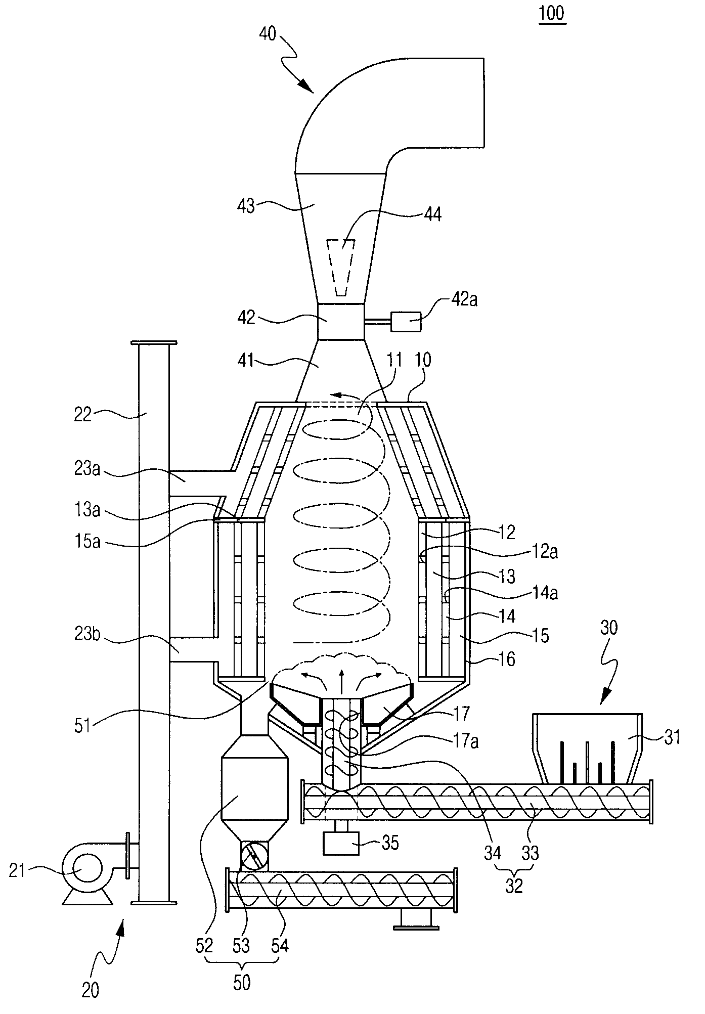
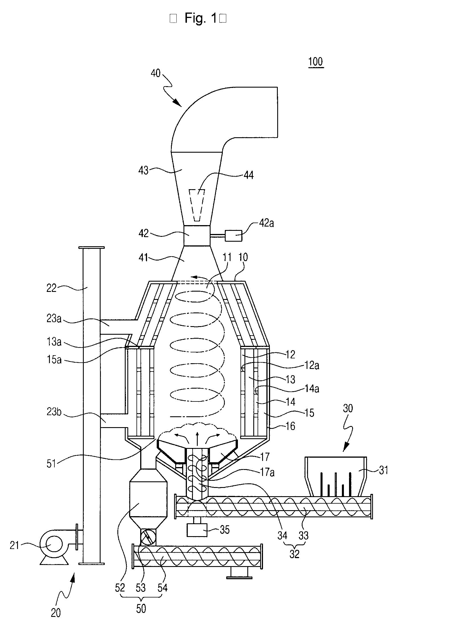
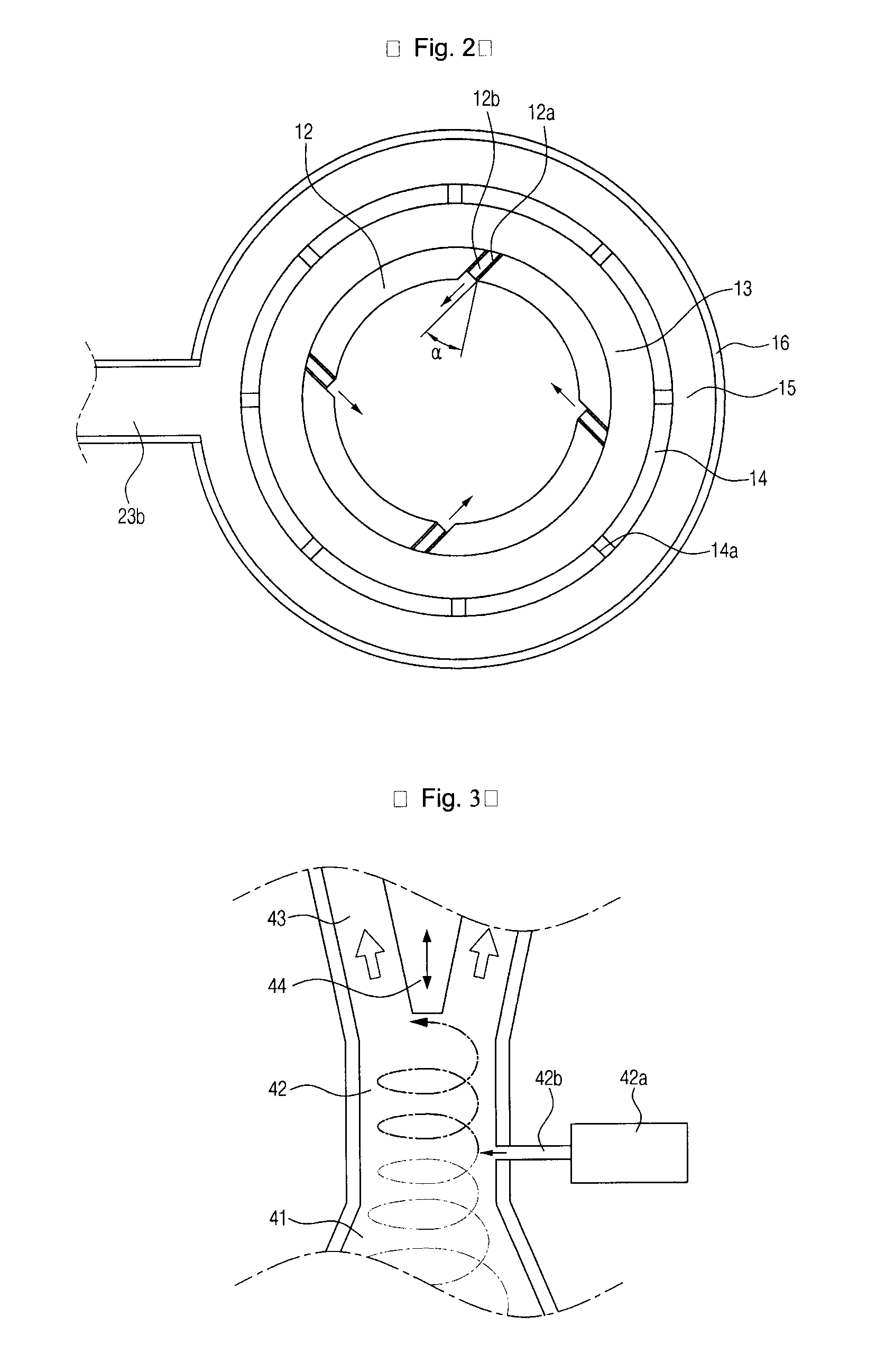
[0024]FIG. 1 is the longitudinal section of a combustion apparatus for recovering heat according to the present invention, FIG. 2 is the cross section of a combustion tank shown in FIG. 1, FIG. 3 is the partially enlarged cross section of a combustion gas exhausting tube shown in FIG. 1, and FIG. 4 is cross section of a narrowed part in the combustion gas exhausting tube shown in FIG. 3.

[0025]A combustion apparatus(100) for recovering heat according to the first preferable embodiment of this invention comprises a combustion tank(10) in which fuel is burned, a combustion air supply part(20), a fuel supply part(30), a combustion gas exhausting tube(40), and an ash discharge part(50).

[0026]Firstly, the combustion tank(10) of cylindrical shape is to receive and burn fuel in the interior, the upper end of the tank(10) is opened to exhaust the combustion gas, on the lower edge of the tank is formed an ash outlet(51) for discharging the burned ash of solid fuel, the outermost side of the t...

second embodiment

[0048]Next, the combustion apparatus for recovering heat(101) according to the present invention is described with reference to the attached drawings.

[0049]The constitution of the combustion apparatus for recovering heat(101) according to the second embodiment of this invention is described only stating the differences from the first embodiment. As compared with the first embodiment, in the combustion apparatus(101) according to the second embodiment, an ash discharge chamber(19) is defined between the combustion chamber(11) and the swirl flow apply chamber(13) of the combustion tank(11), that is to say, the ash discharge chamber(19) is around the outer of the inner wall(12) in the combustion chamber(11), and an ash discharge hole(12c) is defined in the inner wall(12). To this constitution, a space wall(18) is defined between the inner wall(12) and the intermediate wall(14), the ash discharge chamber(19) is defined in the space between the inner wall(12) and the space wall(18), and ...


PUM


Abstract

A combustion apparatus for recovering heat according to the present invention comprising a combustion tank for burning fuel contained in the interior by combustion air supplied from the exterior, characterized in that: a combustion chamber surrounded by an inner wall for burning fuel is defined in said combustion tank; a swirl flow supply chamber for supplying a combustion air into said combustion chamber is defined around the outer circumference of the inner wall of said combustion tank; a combustion air supply passage for supplying combustion air from said swirl flow supply chamber into said combustion chamber is defined on the inner wall of said combustion tank; said combustion air supply passage is slanted at a predetermined angle to the vertical direction of the inner face of the inner wall in said combustion tank; and the combustion air generates a swirl flow in the combustion chamber. Furthermore, the combustion apparatus for recovering heat according to the invention characterized in that; an air cooling chamber for supplying combustion air supplied from the exterior into said swirl flow supply chamber is defined around the outer circumference of said swirl flow supply chamber in said combustion tank, and the combustion air supplied from the exterior is supplied through said cooling chamber into the swirl flow supply chamber to decrease a heat loss and to improve a thermal efficiency.

Description

CROSS-REFERENCE TO RELATED APPLICATION[0001]This application claims the priority benefit of Korean Patent Application No. 10-2007-0117458 filed on Nov. 16, 2007, the contents of which are hereby incorporated by reference as if fully set forth herein in their entirety.STATEMENT CONCERNING FEDERALLY SPONSORED RESEARCH OR DEVELOPMENT[0002]Not applicable.FIELD OF THE INVENTION[0003]This invention relates to a combustion apparatus for recovering heat, more specifically to a combustion apparatus for recovering and utilizing the combustion heat generated in a combustion chamber in which solid fuel is burned.BACKGROUND OF THE INVENTION[0004]Generally, in industrial facilities required for industrial hot water, steam, or high temperature gas, a combustion apparatus is used for generating heat energy by the combustion of fuel in the interior of a combustion tank in order to achieve heat energy, and as a fuel in this combustion apparatus, a solid fuel such as RDF (fuelized life waste) or RPF (...

Claims


Application Information

Patent Timeline
Patent Type & Authority Applications(United States)
IPC IPC(8): F23K3/00F23L1/00F23J1/02
CPCF23B40/04F23G5/165F23G5/24F23L9/00F23G2205/121F23K3/14F23L1/00F23G5/46F23M9/02F23D1/02
Inventor KIM, HONG JIN
Owner ENERONE
Why Eureka
Try Eureka