Solar cell and solar cell module including the same

a solar cell and module technology, applied in the field of solar cells, can solve the problems of reducing the position accuracy of the wiring, damage to the solar cell, and restrictions in the shape and arrangement of the n electrodes, so as to improve the conversion efficiency and the degree of freedom of design

Active Publication Date: 2009-05-21
SANYO ELECTRIC CO LTD
View PDF2 Cites 46 Cited by
  • Summary
  • Abstract
  • Description
  • Claims
  • Application Information

AI Technical Summary

Benefits of technology

[0012]According to this aspect, an n-side bus bar electrode and a p-side bus bar electrode intersect with a linear n finger electrode and p finger electrode on the projection plane parallel to a main surface of a substrate. Hence, the deg...

Problems solved by technology

Thus, a processing for connecting the front surface and the back surface of the respective adjacent solar cells may cause a decrease in a positional accuracy of the wirings, a damage to the solar cells, or the like.
However, in order to insulate the n electrode and the p electrode from each other, there are restrictions in shapes and arrangement of the n electrodes a...

Method used


Image

  • Solar cell and solar cell module including the same
  • Solar cell and solar cell module including the same
  • Solar cell and solar cell module including the same

Examples


first embodiment

Configuration of Solar Cell

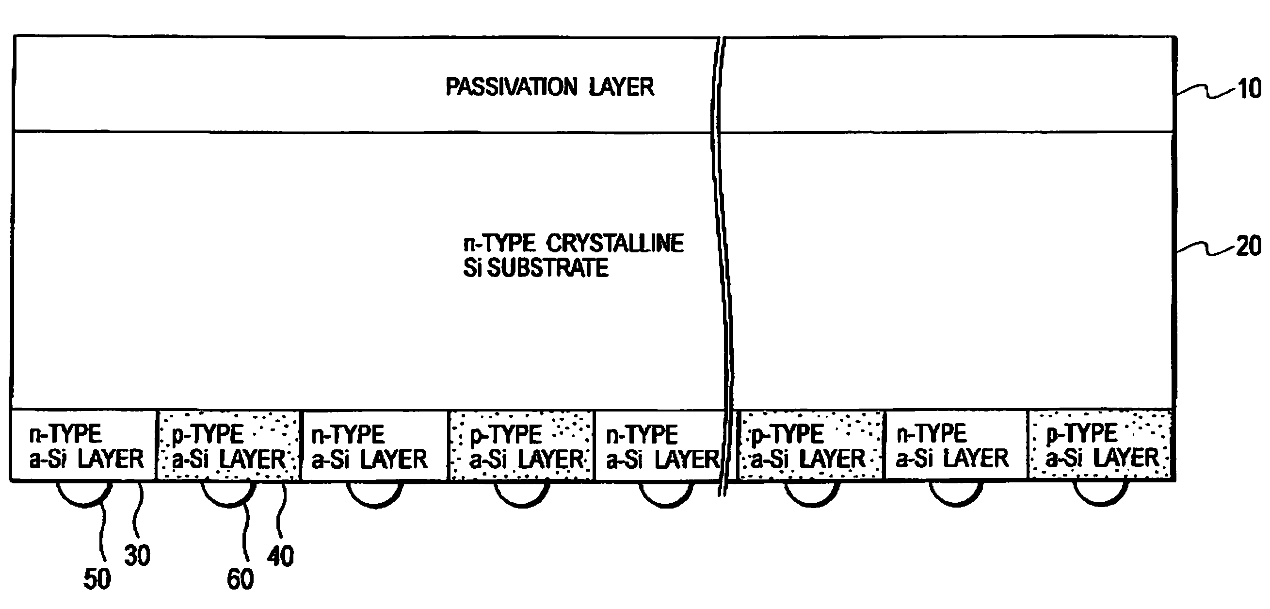
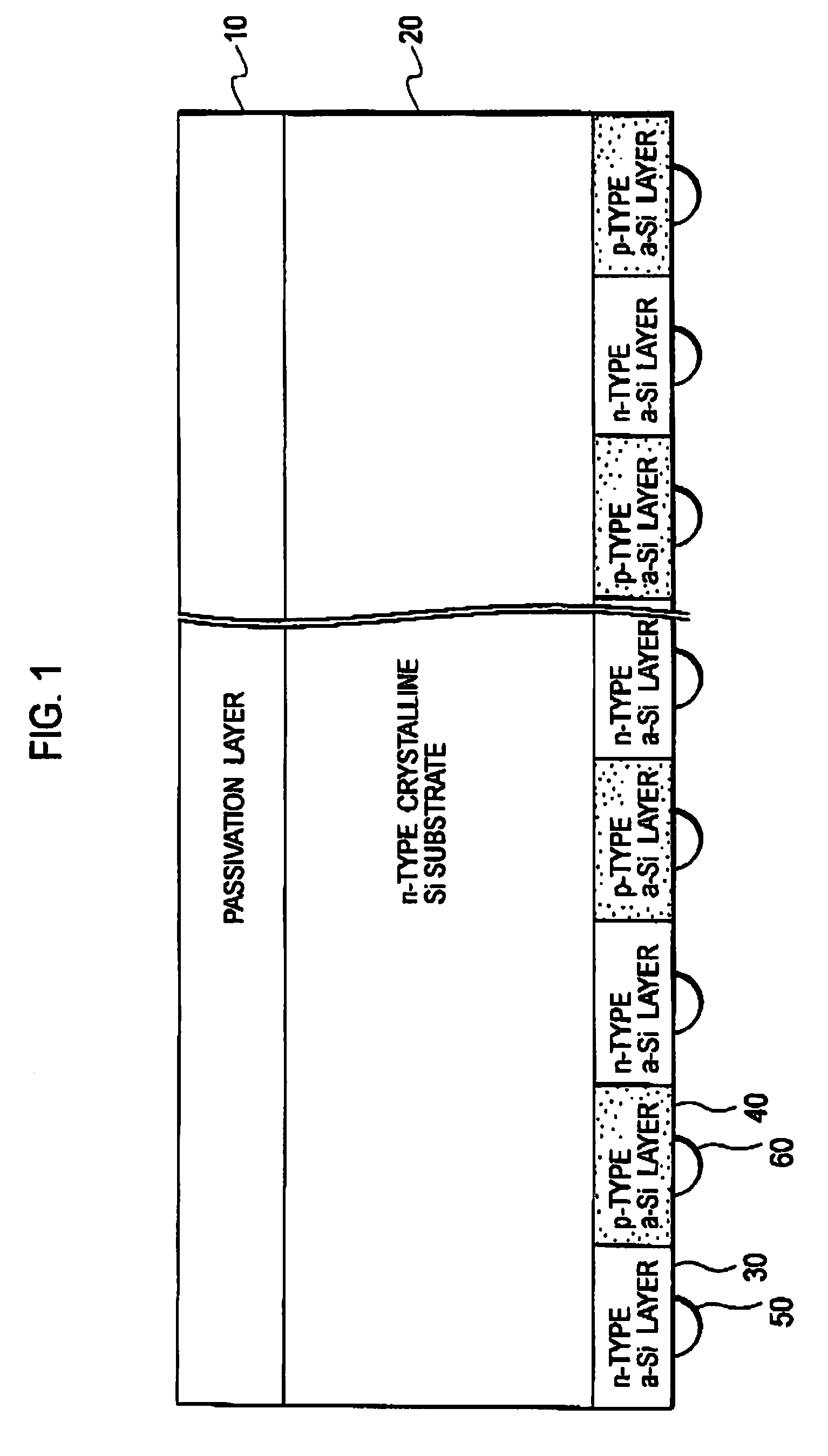
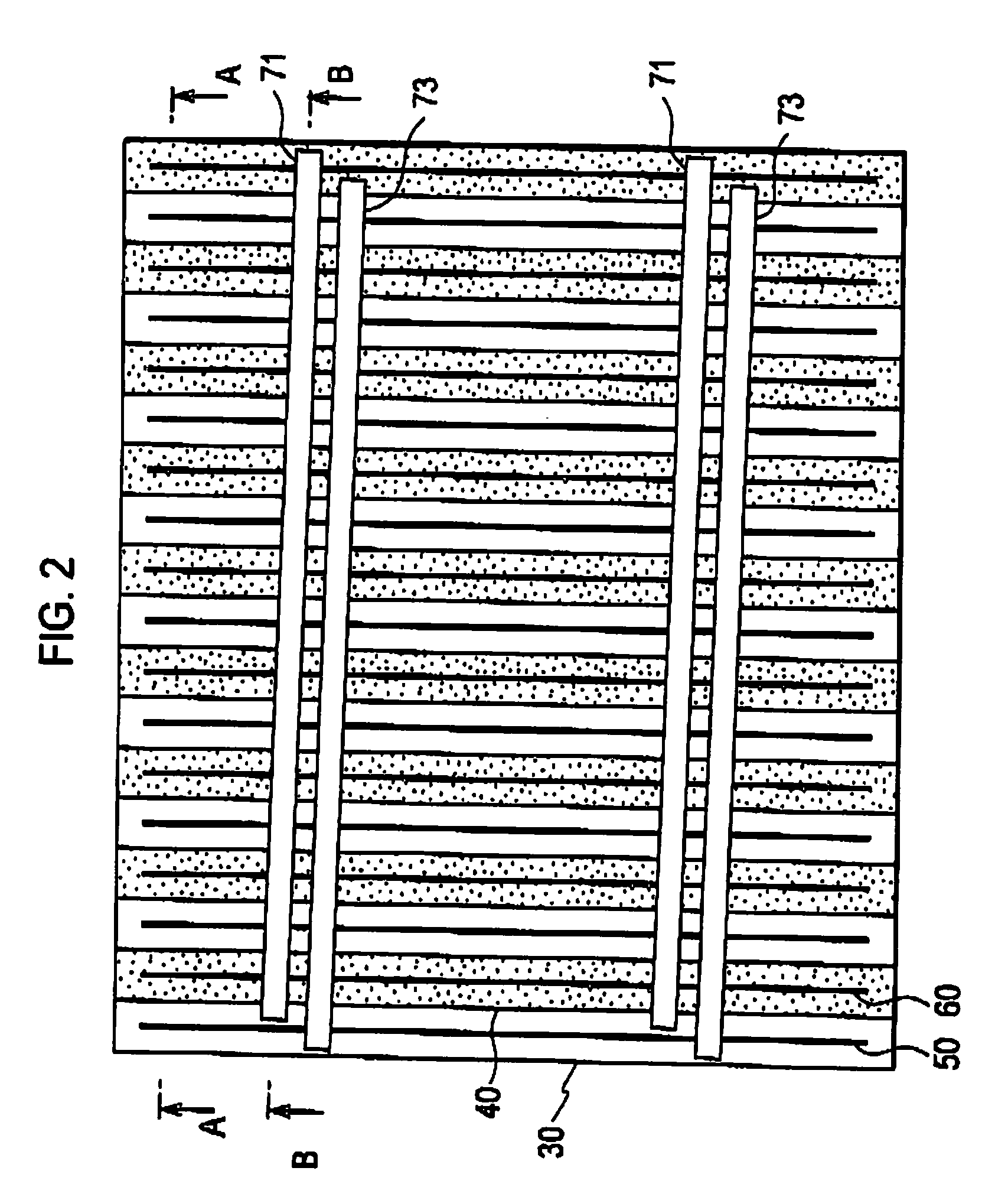
[0034]Hereinafter, the configuration of a solar cell according to a first embodiment of the present invention will be described with reference to the drawings. FIG. 1 is a diagram showing a cross section of a solar cell 100 according to the first embodiment of the present invention. Note that FIG. 1 is a sectional view in which the solar cell 100 is viewed from a direction A shown in FIG. 2 to be described later.

[0035]As shown in FIG. 1, the solar cell 100 includes a passivation layer 10, an n-type crystalline Si substrate 20, an n-type a-Si layer 30, a p-type a-Si layer 40, an n finger electrode 60 and a p finger electrode 60.

[0036]The passivation layer 10 is an amorphous Si layer and configured to have a function of protecting the solar cell 100. Incidentally, the n-type a-Si layer 30 and the p-type a-Si layer 40 may be configured of the crystalline Si same as the n-type crystalline Si substrate 20. Additionally, the amorphous Si layer may be a single la...

second embodiment

[0067]Hereinafter, a second embodiment of the present invention will be described with reference to the drawings. In addition, the difference between the first embodiment described above and the second embodiment will be mainly described.

[0068]More specifically, although the n finger electrode and the p finger electrode are provided on the back surface of the solar cell 100 in the first embodiment described above, the p finger electrode is provided on the front surface of the solar cell 100, and the p bus bar is provided on the back surface of the solar cell 100, in the second embodiment.

(Configuration of Solar Cell)

[0069]Hereinafter, the configuration of a solar cell according to the second embodiment of the present invention will be described with reference to the drawings. FIG. 6 is a diagram showing a cross section of a solar cell 100 according to the second embodiment of the present invention. Note that, FIG. 6(a) is a sectional view in which the solar cell 100 is viewed from a...

third embodiment

[0088]Hereinafter, a third embodiment of the present invention will be described with reference to the drawings. Note that, the difference between the first embodiment described above and the third embodiment will be mainly described below.

[0089]More specifically, although the p-type a-Si layer is provided on the back surface side of the solar cell 100 in the first embodiment as described above, the p-type a-Si layer is provided on the front surface side of the solar cell 100 and the p finger electrode and the p bus bar are provided on the back surface side of the solar cell 100, in the third embodiment.

(Configuration of Solar Cell)

[0090]Hereinafter, the configuration of a solar cell according to the third embodiment of the present invention will be described with reference to the drawings. FIG. 8 is a diagram showing a cross section of a solar cell 100 according to the third embodiment of the present invention. Note that, FIG. 8(a) is a sectional view in which the solar cell 100 is...


PUM


Abstract

Provided is a solar cell in which a linear n finger electrode and a linear p finger electrode are alternately arranged on a projection plane parallel to a main surface of a substrate, and which is arranged in a predetermined arrangement direction, including an n-side bus bar electrode connected to the n finger electrode and insulated from the p finger electrode and a p-side bus bar electrode connected to the p finger electrode and insulated from the n finger electrode. The n-side bus bar electrode and the p-side bus bar electrode are provided on a same main surface side of the substrate, intersect with the n finger electrode and the p finger electrode respectively on the projection plane, and have a slope angle relative to the predetermined arrangement direction.

Description

TECHNICAL FIELD[0001]The present invention relates to a solar cell in which linear n finger electrodes and p finger electrodes are alternately arranged on a projection plane parallel to a main surface of a substrate, and a solar cell module including such solar cells.BACKGROUND ART[0002]In a conventional solar cell module including crystalline Si solar cells, a p-type region is provided on one of a front surface or a back surface of each of the solar cells, while an n-type region is provided on the other one of the front is surface or the back surface of each of the solar cells. In such solar cell modules, a front surface electrode provided on the front surface of one solar cell is connected to a back surface electrode provided on the back surface of a different solar cell adjacent to the one solar cell with wirings (e.g., Japanese Patent Publication No. 3670834 (see claim 1, [0017], FIG. 2, and the like).[0003]In this solar cell module, the front surface electrode of the one solar ...

Claims


Application Information

Patent Timeline
IPC IPC(8): H01L31/042H01L31/00
CPCY02E10/50H01L31/022458H01L31/0747H01L31/0516H01L31/0682H01L31/02245Y02E10/547H01L31/04
Inventor HISHIDA, YUJITAIRA, SHIGEHARU
Owner SANYO ELECTRIC CO LTD
Why Eureka
Try Eureka