

Tire with zoned built-in sealant layer
- Summary
- Abstract
- Description
- Claims
- Application Information
AI Technical Summary
Benefits of technology
Problems solved by technology
Method used
Image

Examples
example ii
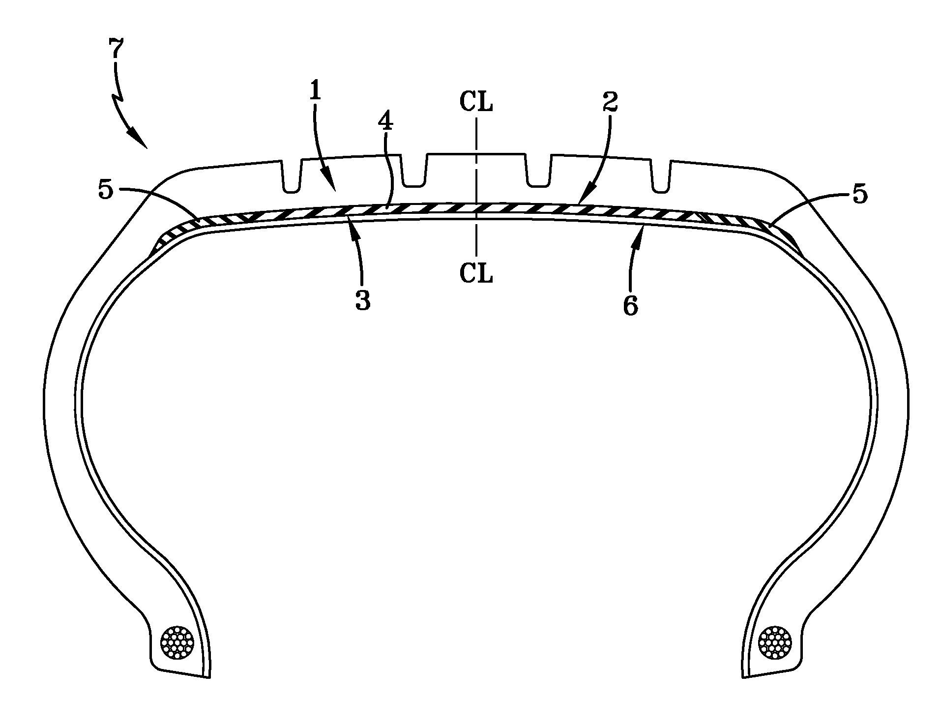
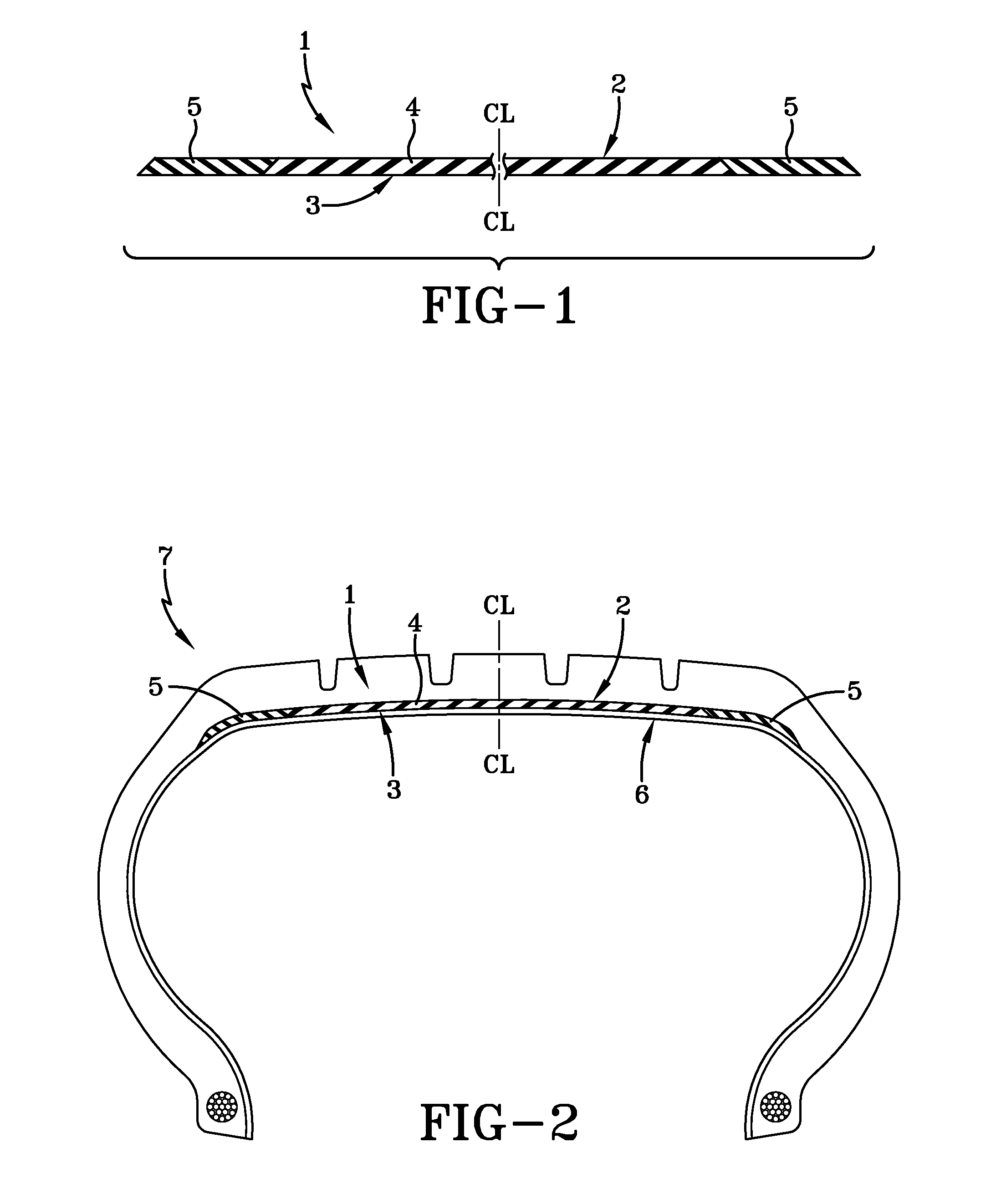
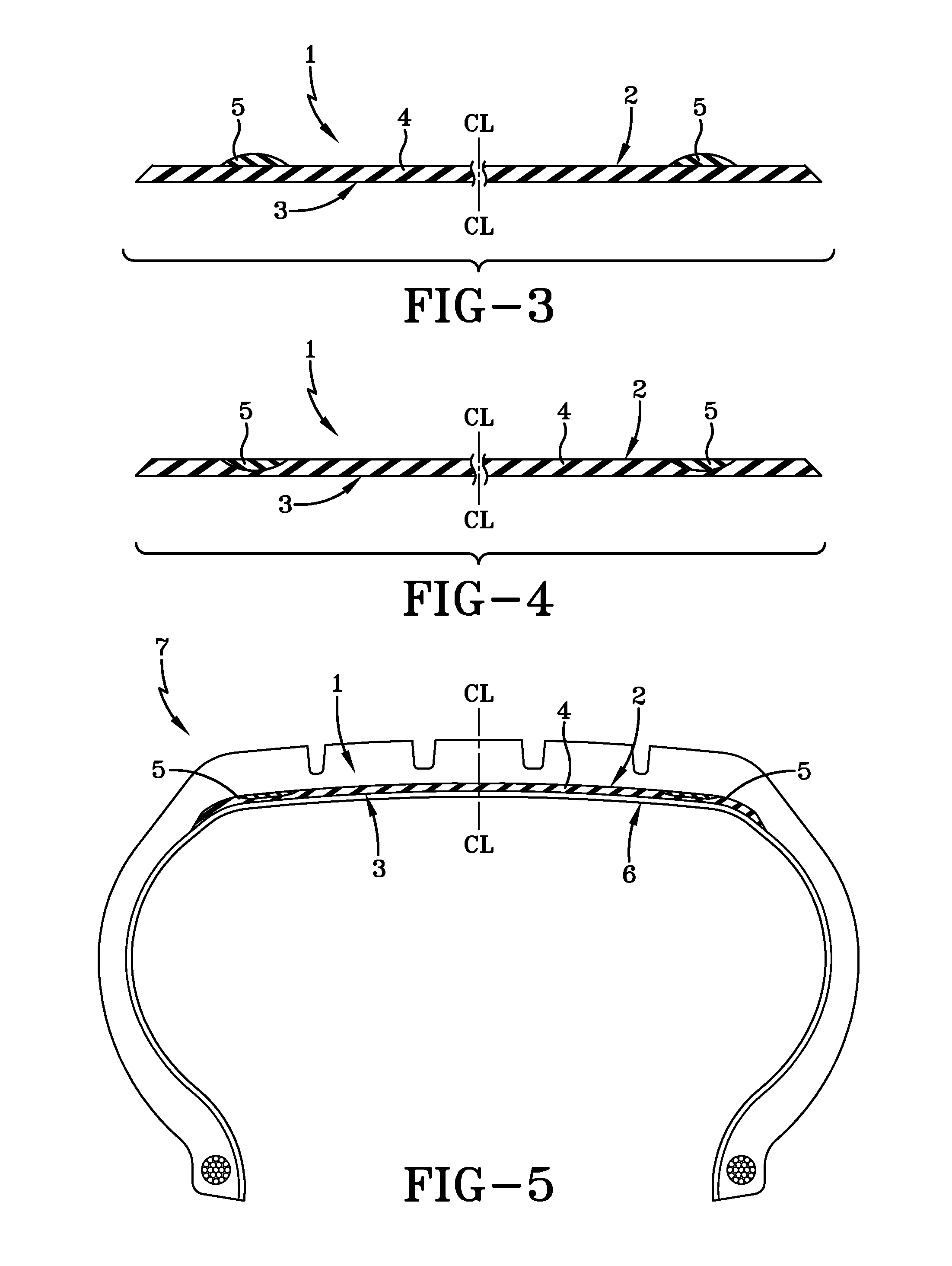
[0116]A tubeless pneumatic steel belted medium radial truck tire is prepared by first applying a standard butyl rubber innerliner layer (e.g. bromobutyl rubber composition) to a standard building drum. Then a zoned layer of butyl rubber-based sealant precursor similar to FIG. 1 composed of lateral zones comprised of the composition of Sample B of Example I and a central zone comprised of the composition of Sample A of Example I having a thickness of about 0.76 cm (about 0.3 inches) is applied to the innerliner layer on the building drum followed by application of diene rubber based carcass components, including the carcass plies, tread, sidewalls and beads, to form the uncured, or green, tire construction, or assembly, which contains the zoned butyl rubber-based sealant precursor layer.
[0117]The green tire is cured in a suitable tire curing mold at an elevated temperature to form a tire with a built-in sealant layer similar to FIG. 2 having a thickness of about 0.38 cm (about 0.15 i...
PUM
| Property | Measurement | Unit |
|---|---|---|
| Temperature | aaaaa | aaaaa |
| Fraction | aaaaa | aaaaa |
| Fraction | aaaaa | aaaaa |
Abstract
Description
Claims
Application Information