
Method and apparatus for forced air heater measurement and control

Active Publication Date: 2009-05-21
EIT 2 0 LLC
View PDF16 Cites 8 Cited by
  • Summary
  • Abstract
  • Description
  • Claims
  • Application Information

AI Technical Summary

Benefits of technology

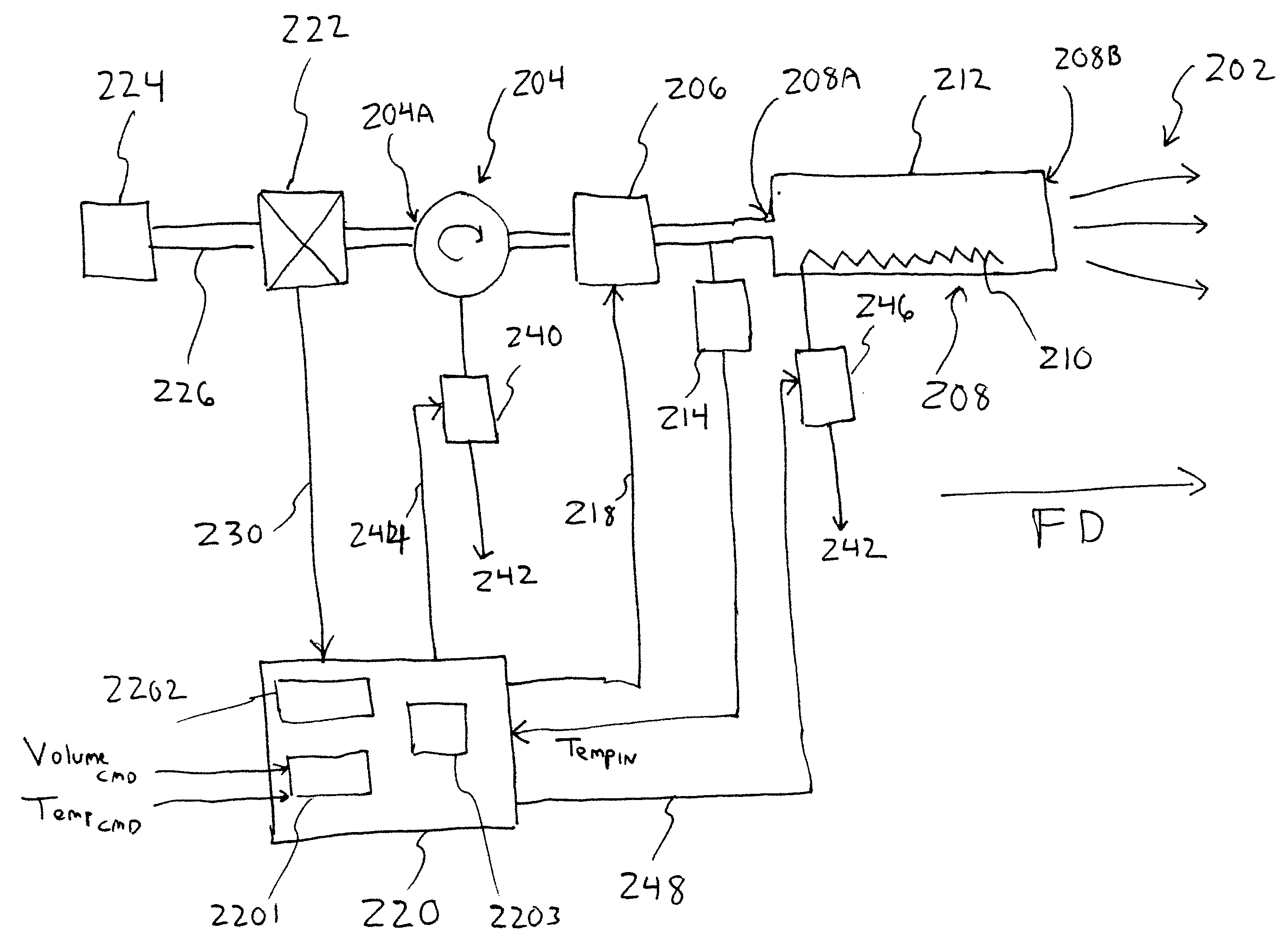
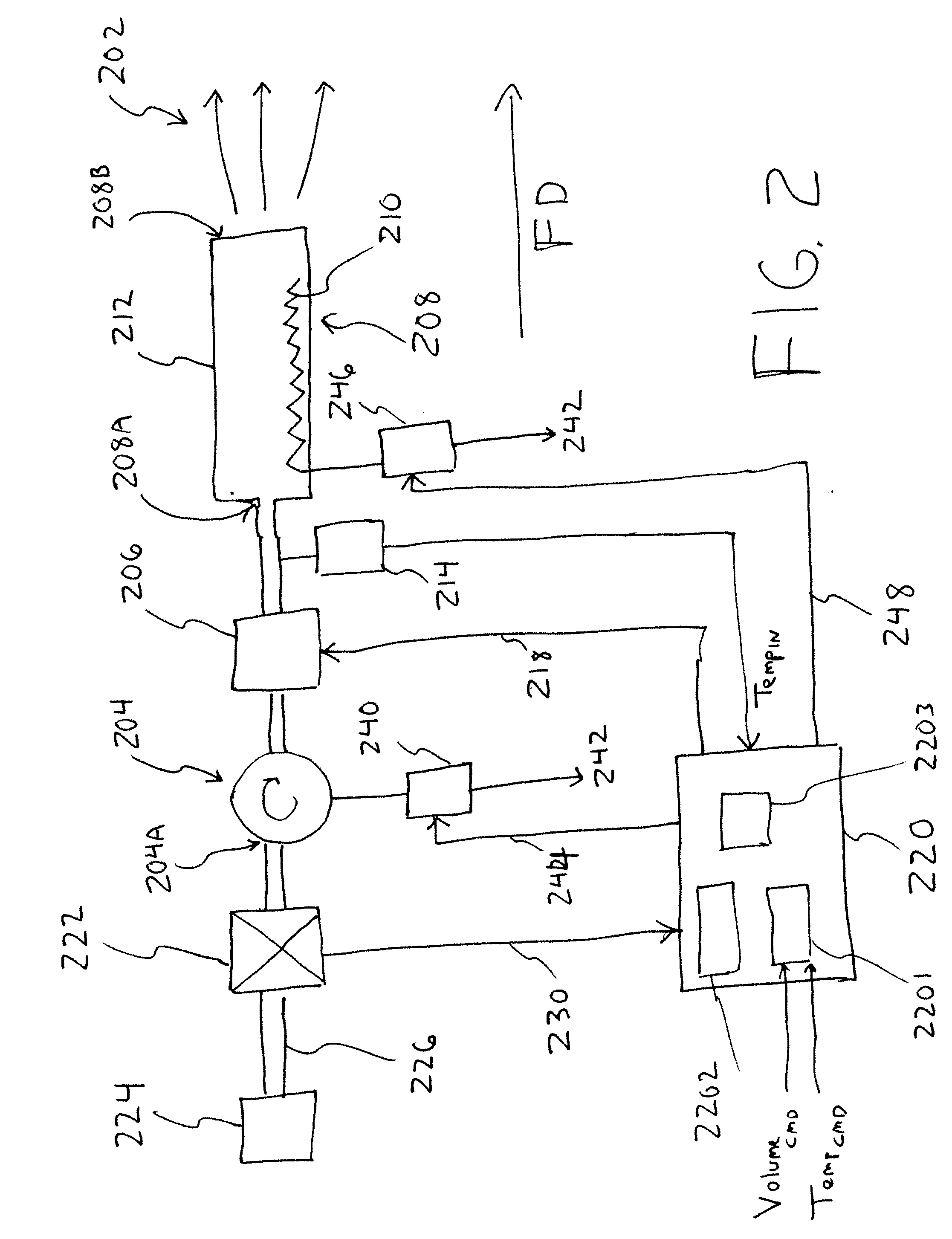
[0011]One example according to one embodiment includes an air blower connected to an electrical air heater, the heater having a tube or equivalent and a heater exhaust nozzle output port, the example having a mass flow sensor for detecting a mass flow of air through the air blower, an input temperature sensor for detecting temperature of air entering the electrical air heater, and a controller for controlling the air flow urged by the blower and for controlling power to the electrical air heater, the controller arranged to control the air flow urged by the air blower based on a received air flow rate command, and arranged to control the power to the electrical air heater based on a received air output temperature command, the received air flow rate command and the detected mass flow through the air blower. According to one example, the control of the air flow urged by the air blower may be implemented by including an air throttle in the air path preceding the electrical air heater, and arranging the controller to control the air throttle. According to another example, the control of the air flow urged by the air blower may be implemented by a controllable power air blower and arranging the controller to control the air blower.
[0012]According to one aspect, the controller is arranged to control power to the electrical air heater by generating an electrical air heater power control signal proportional to an arithmetic product of the air out

Problems solved by technology

Another is that thermocouples may have a high failure rate, and failures typically result in lost production time and output.
For example, a thermocouple failure may result in the heated air 16 being so hot that significant quantities of product are damaged or destroyed before the failure is detected.
Further, thermocouples typically deteriorate over time, due to their intense heat exposure.
Placing the thermocouple in a well is one known method for reducing this heat deterioration but, because of the distance between the flow and the well and because of reduced air flow on the thermocouple, the result is a significant delay between changes in the temperature of the air flow and corresponding changes in the thermocouple measurement.
This time delay can have detrimental effects on the temperature control loop.
Further, even at a steady state air flow temperature, the temperature in the well may be hotter or colder than the air flow temperature, thereby further causing inaccurate the temperature control.
However, such vane switches and other air flow detector devices often have such a delay time that, if air flow ceases, the heating element 14A is destroyed before power is switched off.
Equally significant is that such airflow detector switches and devices often have a high mechanical failure rate.

Method used


Image

  • Method and apparatus for forced air heater measurement and control
  • Method and apparatus for forced air heater measurement and control
  • Method and apparatus for forced air heater measurement and control

Examples


Embodiment Construction

[0018]It is to be understood that the present invention is not limited to the specific examples described herein or depicted by the attached drawings, and that other configurations and arrangements can, upon reading this description, be readily implemented by persons skilled in the pertinent arts.

[0019]In the drawings, like numerals appearing in different drawings, either of the same or different embodiments of the invention, reference functional or system blocks that may be identical or substantially identical between the different drawings.

[0020]It is to be understood that the various embodiments of the invention, although different, are not necessarily mutually exclusive. For example, a particular feature, function, act or characteristic described in one embodiment may, within the scope of the invention, be included in other embodiments.

[0021]Various instances of the phrase “in one embodiment” do not necessarily refer to the same embodiment.

[0022]The terms “comprising”, “includin...


PUM

PropertyMeasurementUnit
Temperatureaaaaaaaaaa
Flow rateaaaaaaaaaa
Mass flow rateaaaaaaaaaa

Abstract

A blower urges an airflow, at a rate according to a user-controlled flow rate command, through an electric heater and the electrical heater heats the airflow at a heater power based on a user-input temperature command, the user-input flow rate command, and a measured mass flow rate of the airflow. The heater power is calculated based on the heat energy required to heat air to the given reference temperature, at a flow rate corresponding to the measured mass flow rate. Optionally, the temperature of the air entering the electric heater is measured, and the heater power is calculated based on the heat energy required to heat air from the measured temperature to the given reference temperature, at a flow rate corresponding to the measured mass flow rate.

Description

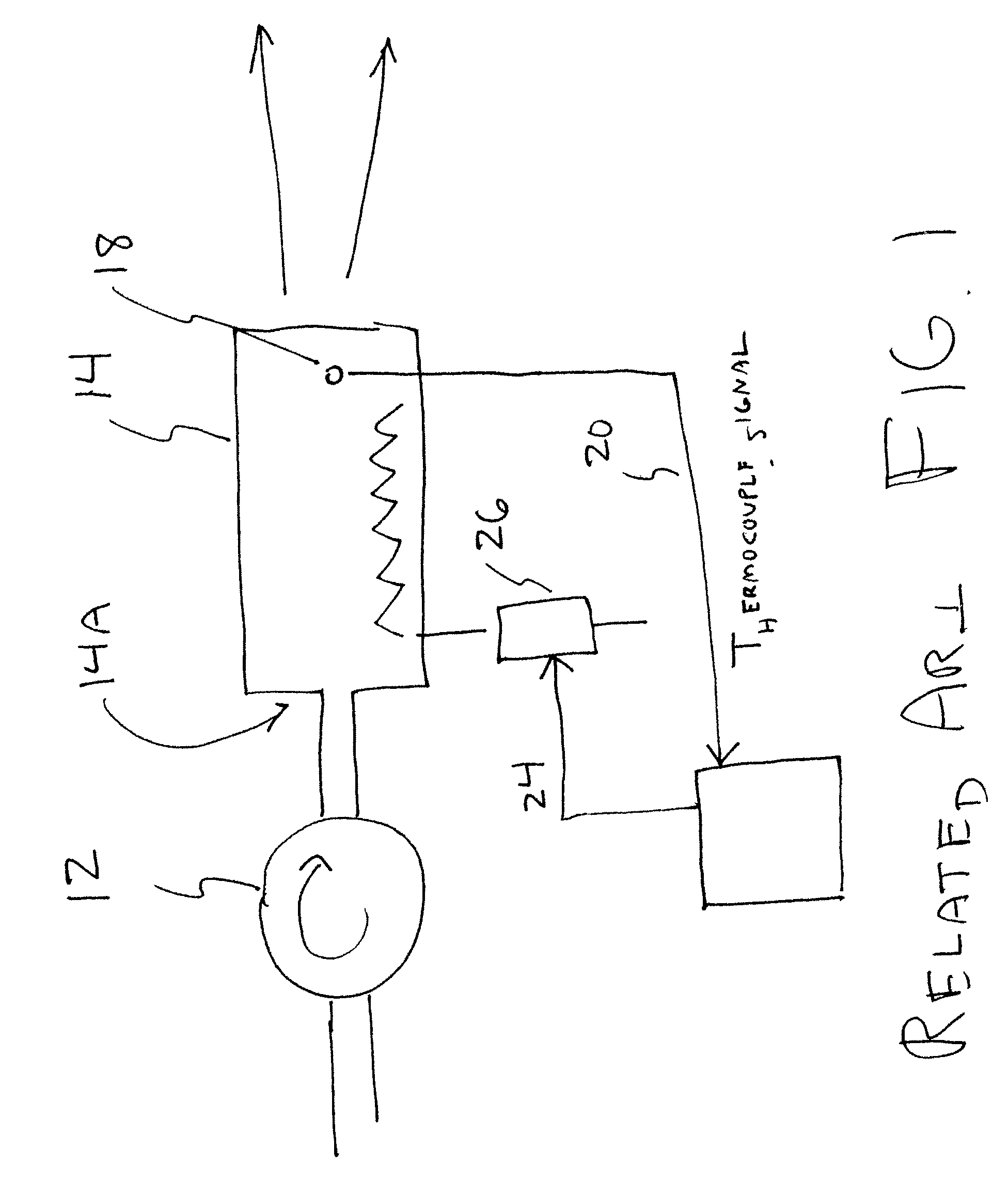
TECHNICAL FIELD[0001]The field of the invention is heated forced air delivery, more specifically, a forced air heater providing an airflow controlled at a selected temperature and at a selected mass flow rate or at a selected air velocity.BACKGROUND OF THE INVENTION[0002]High power air heaters are used, for example, in manufacturing and other commercial applications and may have up to, for example, approximately thirty kilowatts (kW) of power. Example applications include, without limitation, heat shrink wrapping, drying / curing of surface coatings and thermal reflow adhesives, and heating of materials for forming purposes.[0003]Related Art FIG. 1 shows a typical related art heated air system 10, having a blower 12 connected to a heater tube 14 having a resistance or other type of electrical heating element 14A, to output heated air 16. For the remainder of this description, unless otherwise stated, the phrase “electrical heating element” means any element that converts electrical en...

Claims


Application Information

Patent Timeline
IPC IPC(8): F24D5/00B22F1/068B22F1/10
CPCF24D5/02F24D19/1084F24D19/1096F24H3/022F24H3/0411H05K9/0088B22F1/0055B22F1/0059B22F2998/10H05K9/0083F24H9/2064B22F1/10B22F1/068F24H15/204F24H15/148F24H15/395F24H15/414F24H15/238F24H15/281F24H15/35F24H15/37F24H15/31
Inventor MAY, JOE T.
Owner EIT 2 0 LLC
Learn More