
Semiconductor device and manufacturing method thereof

a semiconductor device and manufacturing method technology, applied in the field of semiconductor devices, can solve problems such as the deterioration of the reliability of the semiconductor device b>100/b>, and achieve the effect of improving reliability

Active Publication Date: 2009-05-21
SHINKO ELECTRIC IND CO LTD
View PDF6 Cites 4 Cited by
  • Summary
  • Abstract
  • Description
  • Claims
  • Application Information

AI Technical Summary

Benefits of technology

[0027]The present invention is achieved in view of the circumstance and an object of the present invention is to provide a semiconductor device having enhanced reliability and also to provide a manufacturing method thereof.
[0058]In accordance with the invention, it is possible to provide a semiconductor device and a manufacturing method thereof, capable of reducing the manufacturing cost of the semiconductor device, and capable of improving the yield and reliability of the semiconductor device.

Problems solved by technology

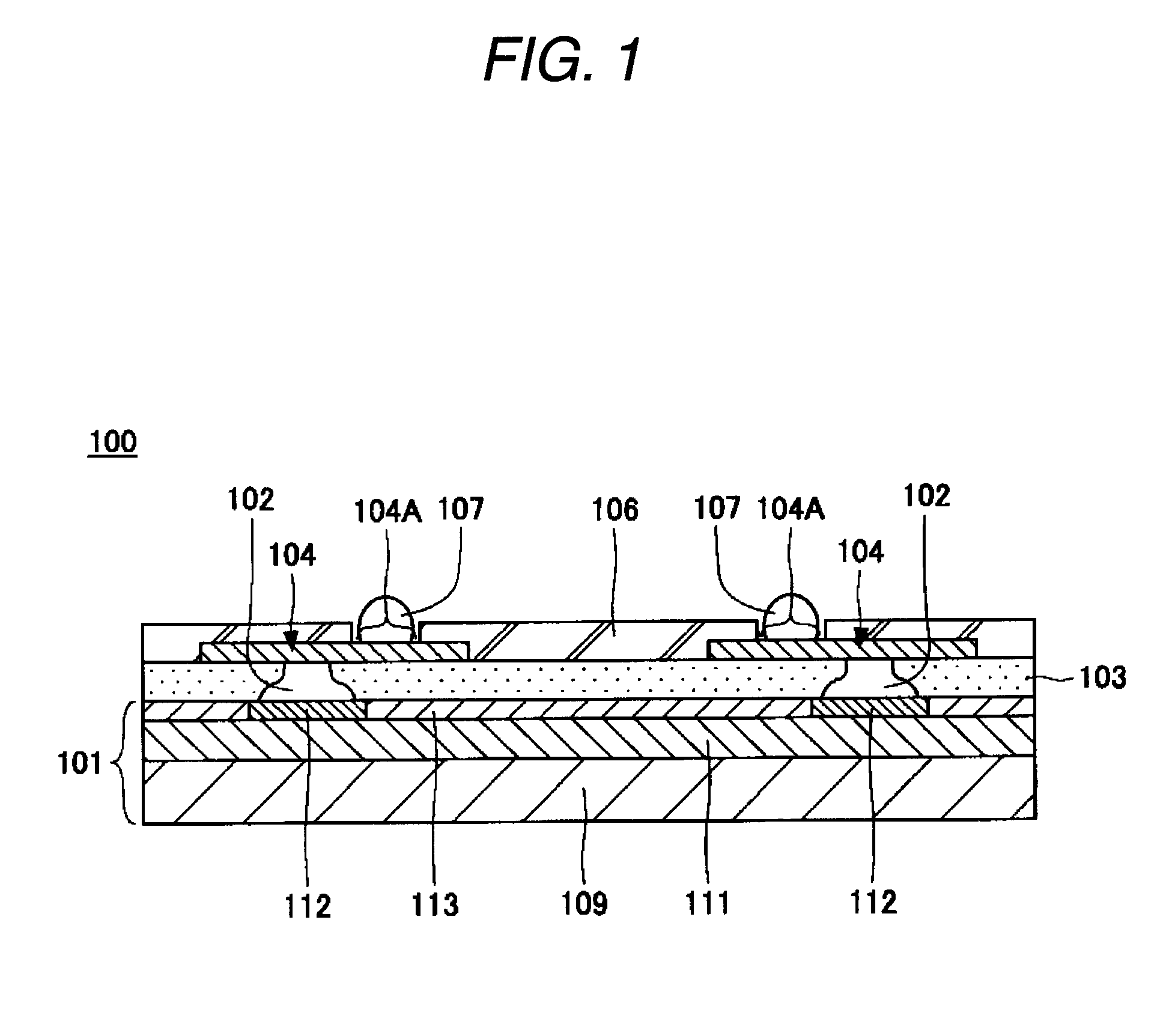
Thus, there is a problem that a reliability of the semiconductor device 100 deteriorates due to the peeling of the resin layer 103 from the corner portion.

Method used


Image

  • Semiconductor device and manufacturing method thereof
  • Semiconductor device and manufacturing method thereof
  • Semiconductor device and manufacturing method thereof

Examples


first embodiment

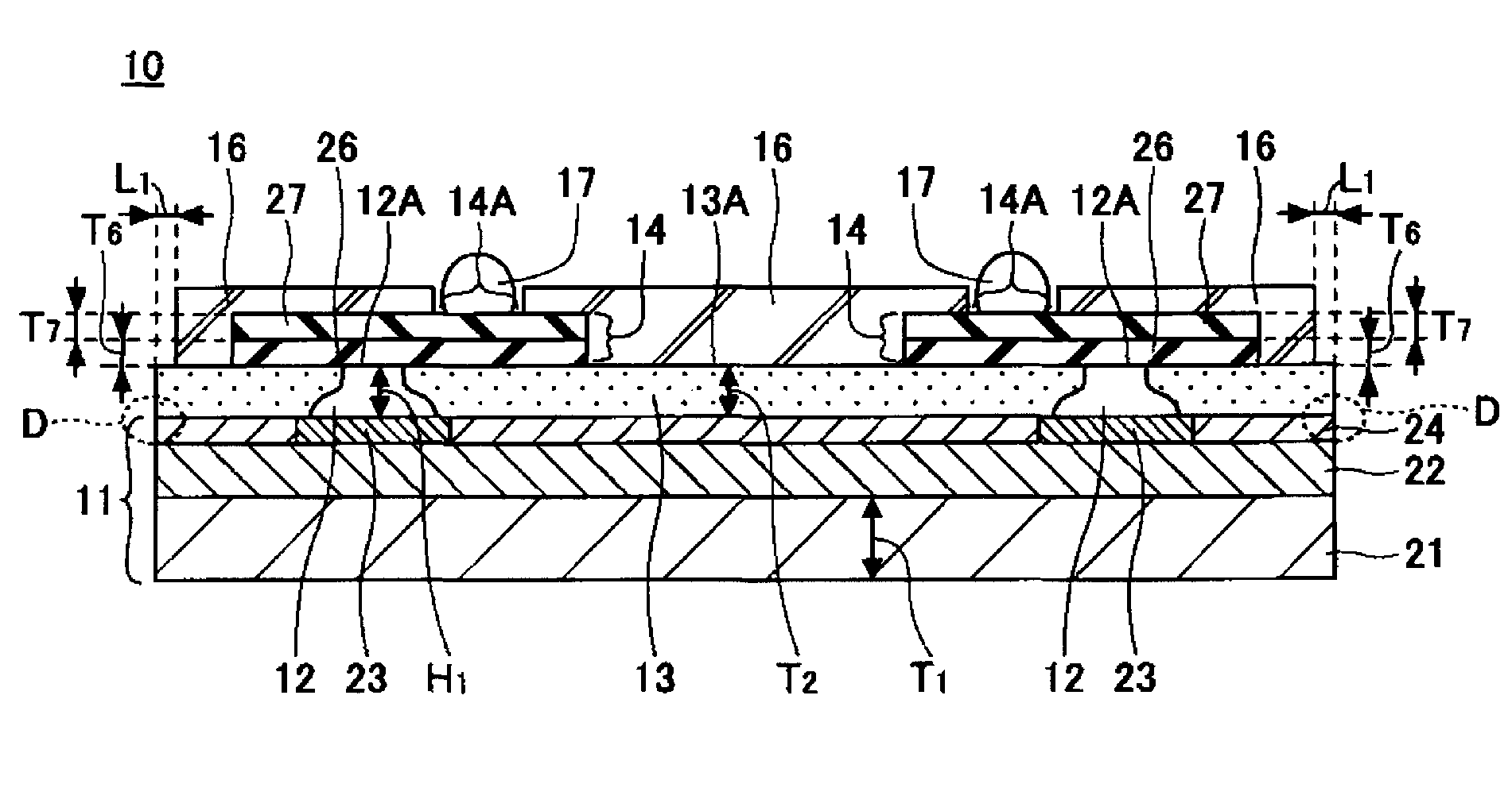
[0088]FIG. 3 is a cross sectional view of a semiconductor device of a first embodiment of the invention. As shown in FIG. 3, a semiconductor device 10 of the first embodiment has a semiconductor chip 11, internal connection terminals 12, an insulation layer 13 (first insulation layer), a wiring pattern 14 including a metal layer 26 and a second metal layer 27, a solder resist 16 (second insulation layer), and external connection terminals 17. Here, a D part denotes a portion where a peeling off is unfavorably caused in a conventional semiconductor device. That is, a boundary between a protective layer 24 and the first insulation layer 13, which adjoins to a scribe region B explained later.

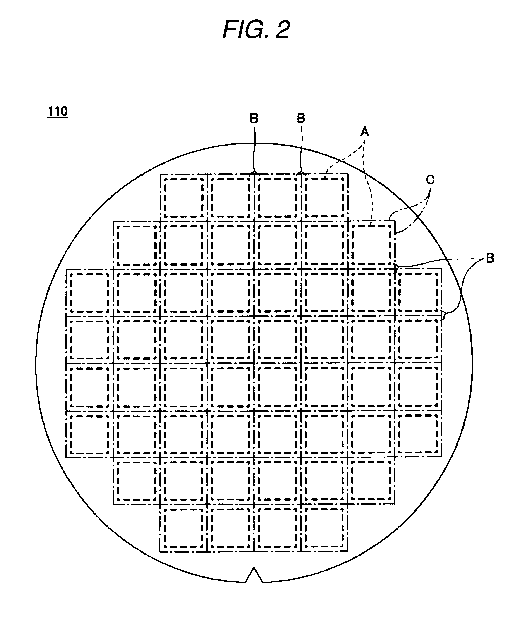
[0089]FIG. 4 is a plan view of a semiconductor substrate on which the semiconductor devices of the first embodiment of the invention are formed. In FIG. 4, 31 denotes a semiconductor substrate, and C denotes a position at which the semiconductor substrate 31 is cut by a dicer (which is hereinafter ...

second embodiment

[0120]FIG. 21 is a cross sectional view of a semiconductor device in accordance with a second embodiment of the invention. In FIG. 21, the same constituent parts as those of the semiconductor device 10 of the first embodiment are given the same reference numerals and signs. By reference to FIG. 21, a semiconductor device 40 of the second embodiment is configured in the same manner as the semiconductor device 10, except that a wiring pattern 41 including a metal layer 26 is provided in place of the wiring pattern 14 including the metal layer 26 and the second metal layer 27 provided in the semiconductor device 10 of the first embodiment.

[0121]FIGS. 22 to 28 are views showing the manufacturing steps of the semiconductor device in accordance with the second embodiment of the invention. In FIGS. 22 to 28, the same constituent parts as those of the semiconductor device 40 of the second embodiment are given the same reference numerals and signs. By reference to FIGS. 22 to 28, a descripti...


PUM


Abstract

A method for manufacturing a semiconductor device has preparation step of preparing a semiconductor substrate having a plurality of semiconductor chip formation regions and a scribe region arranged between the plurality of the semiconductor chip formation regions and including a substrate cutting position, a semiconductor chip formation step of forming semiconductor chips having electrode pads on the plurality of semiconductor chip formation regions, a first insulation layer formation step of forming a first insulation layer on the semiconductor chips and the scribe region of the semiconductor substrate, a second insulation layer formation step of forming a second insulation layer on the first insulation layer except for a region corresponding to the substrate cutting position, and a cutting step of cutting the semiconductor substrate at the substrate cutting position.

Description

BACKGROUND OF THE INVENTION[0001]1. Field of the Invention[0002]The present invention relates to a semiconductor device and a manufacturing method thereof. More particularly, it relates to a semiconductor device which is generally equal in size to a semiconductor chip in plan configuration, and in which the semiconductor chip is flip-chip connected to a wiring pattern, and a manufacturing method thereof.[0003]2. Description of Related Art[0004]In recent years, semiconductor applied products have rapidly advanced in size reduction, thickness reduction, and weight reduction as various mobile devices such as digital cameras and cellular phones. Accordingly, a semiconductor device has been also required to be reduced in size, and increased in density. Thus, there has been developed a semiconductor device (see, e.g., FIG. 1) referred to as a so-called chip size package (CSP) configured to be generally equal in size to a semiconductor chip thereof in plan configuration, and there have bee...

Claims


Application Information

Patent Timeline
Patent Type & Authority Applications(United States)
IPC IPC(8): H01L21/304H01L23/58
CPCH01L21/78H01L23/3114H01L23/3192H01L2924/14H01L24/10H01L2924/01078H01L2924/01079H01L23/49816H01L2224/02333H01L2224/05124H01L2224/05144H01L2224/05155H01L2224/05647H01L2924/00014H01L23/12
Inventor YAMANO, TAKAHARUMACHIDA, YOSHIHIRO
Owner SHINKO ELECTRIC IND CO LTD
Learn More