Hydroelectric device for harnessing the buoyant force of an object in a fluid

Inactive Publication Date: 2009-05-21
COOK LARRY
View PDF1 Cites 13 Cited by
  • Summary
  • Abstract
  • Description
  • Claims
  • Application Information

AI Technical Summary

Benefits of technology

[0026]The volume of fluid contained within the housing has a first density, and the at least one buoy has a second density. The first density is greater t

Problems solved by technology

Regardless of the specific type or configuration of water wheel employed, conventional water wheels suffer from drawbacks related to the body of water in which they are situated.
In areas in which no suitable body of water is present, the ability to use a water wheel is lost.
Time and resources used to place a water wheel in a suitable body of water can later be lost when the body of water changes sufficiently that the water wheel no longer generates a required amount of power.
As global temperatures changes and the incidence of drought increases in some geographic areas, those areas that may once have relied on water wheels may find the ability to continue that reliance to be limited.

Method used


Image

  • Hydroelectric device for harnessing the buoyant force of an object in a fluid
  • Hydroelectric device for harnessing the buoyant force of an object in a fluid
  • Hydroelectric device for harnessing the buoyant force of an object in a fluid

Examples


Embodiment Construction

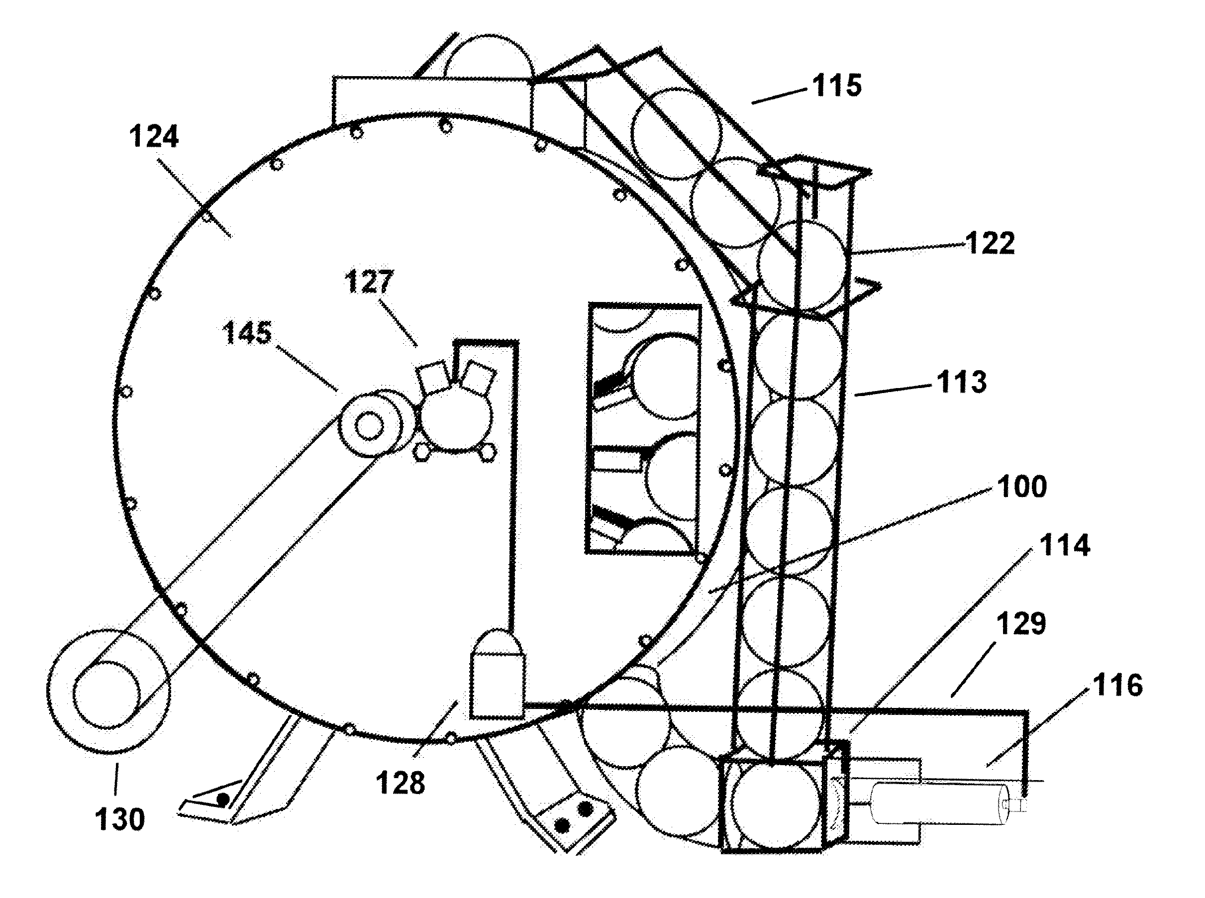
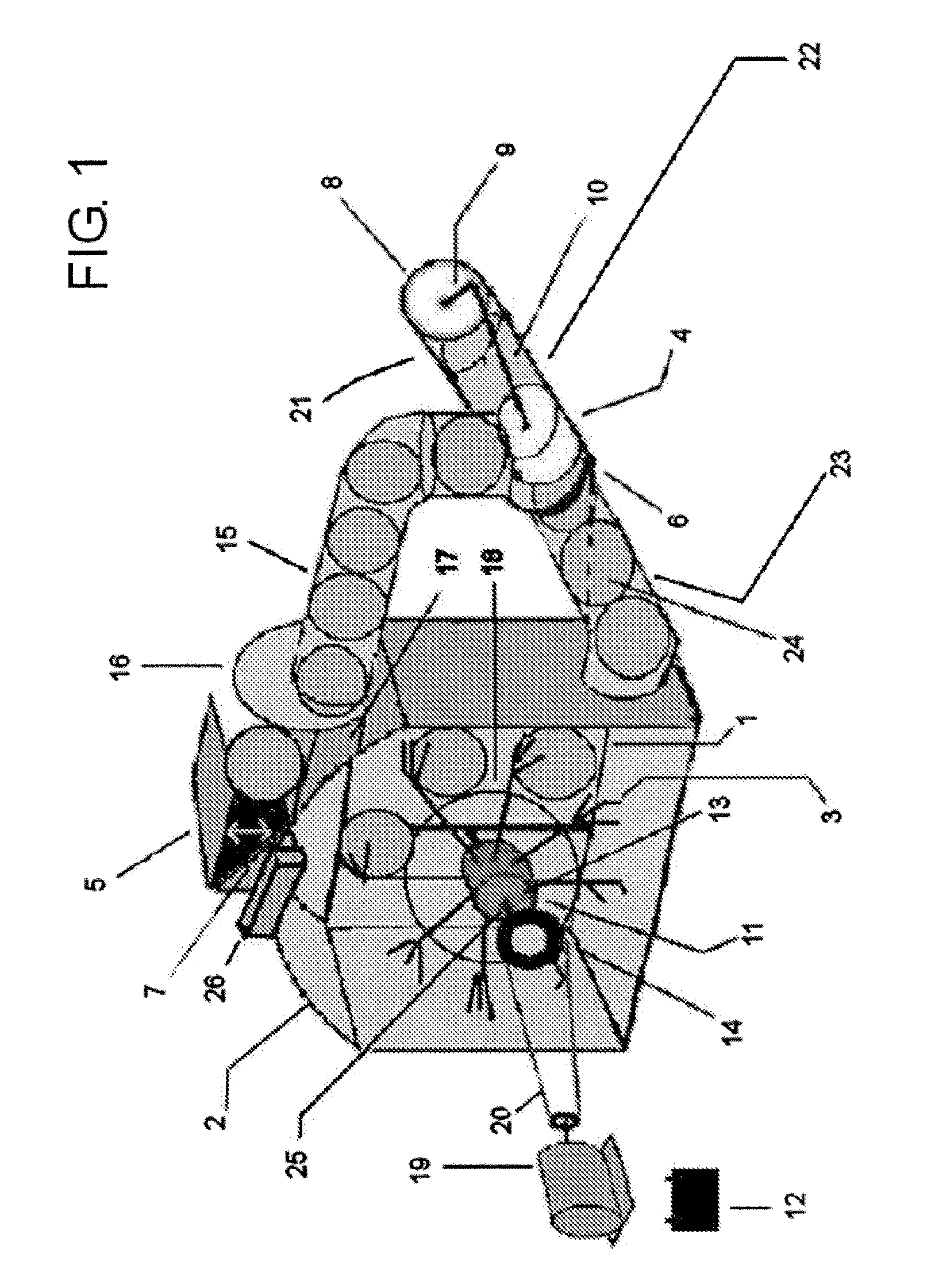
[0036]The present invention provides a device that combines the general principles of the water wheel with a novel configuration designed to harness the properties of buoyant objects, so that the water wheel principles can be implemented without the geographical and other limitations of a conventional water wheel. A detailed discussion of one embodiment of the present invention, shown in FIG. 1, is now provided, followed by a more general discussion of this and alternative embodiments of the present device.

[0037]As shown in FIG. 1, the present device includes a tank or housing 2, in which the primary power-producing components of the present device are located. Located within housing 2 is a rotor hub 11 mounted on a shaft 13. Protruding from shaft 13 are a plurality of supports 18 that terminate in fins 3. In addition to having rotor hub 11 mounted thereon, shaft 13 also engages a pulley 14, which rotates as the rotation of shaft 13 imparts rotational energy thereto. Pulley 14 is as...


PUM


Abstract

The present invention provides, in one embodiment, a device for producing electricity, the device including a housing having a volume of fluid therein, a rotor within the housing, the rotor being in fluid communication with the housing and fixedly attached to a shaft. At least one buoy is sized and shaped to move through the fluid in housing, as well as though an inlet and outlet of the housing. An electrical generator is coupled to the shaft to which the rotor is attached. When a buoy moved into the housing through the inlet, it rises in the fluid and is received by the rotor, causing the rotor to turn as the buoy continues to rise. The turning of the rotor operates the electrical generator.

Description

CROSS-REFERENCE TO RELATED APPLICATIONS[0001]This Application claims priority of U.S. Provisional Patent Application No. 60 / 988,760, filed on Nov. 16, 2007, which is hereby incorporated by reference in its entirety.STATEMENT REGARDING FEDERALLY SPONSORED RESEARCH OR DEVELOPMENT[0002]Not Applicable.INCORPORATION BY REFERENCE OF MATERIAL SUBMITTED ON A COMPACT DISC[0003]Not Applicable.BACKGROUND OF THE INVENTION[0004]The present invention relates generally to a hydroelectric energy-producing device, and more specifically to a device adapted to harness the buoyancy of objects to produce energy or perform work.[0005]For thousands of years, mankind has harnessed the power of water to produce energy and perform work. Ancient Greeks used water wheels to grind wheat into flour more than two-thousand years ago. Later, during the height of the Roman Empire, water wheel technology spread throughout Europe. Over the subsequent millennia, hydropower technology has spread to a variety of applicat...

Claims


Application Information

Patent Timeline
IPC IPC(8): F02B63/04
CPCY02E10/20F03B17/02
Inventor COOK, LARRY
Owner COOK LARRY
Why Eureka
Try Eureka