Input apparatus and optical mouse for computer and operation method thereof

a technology of input apparatus and optical mouse, which is applied in the field of input apparatus for computer system and operation method thereof, can solve the problems of inability to provide a convenient input method, still not so realistic, and application to fixed hosts, and achieve the effects of less limitation, more intuitive, flexible and practicabl

Inactive Publication Date: 2009-05-21
ASUSTEK COMPUTER INC
View PDF18 Cites 4 Cited by
  • Summary
  • Abstract
  • Description
  • Claims
  • Application Information

AI Technical Summary

Benefits of technology

[0023]Since the input apparatus of the present invention includes a prime motion detector having an image detection unit and a G-sensor, which may detect a movement state of the prime motion detector in the three-dimensional space. Therefore, a user may operate the computer system with a more intuitive, realistic and less limitation manner. Moreover, in the present invention, a receiver is ap

Problems solved by technology

However, under some special circumstances, for example, computer game playing, the conventional input apparatus cannot provide a convenience input method.
Though operation of the computer game can be more interesting via such special input

Method used


Image

  • Input apparatus and optical mouse for computer and operation method thereof
  • Input apparatus and optical mouse for computer and operation method thereof
  • Input apparatus and optical mouse for computer and operation method thereof

Examples


first embodiment

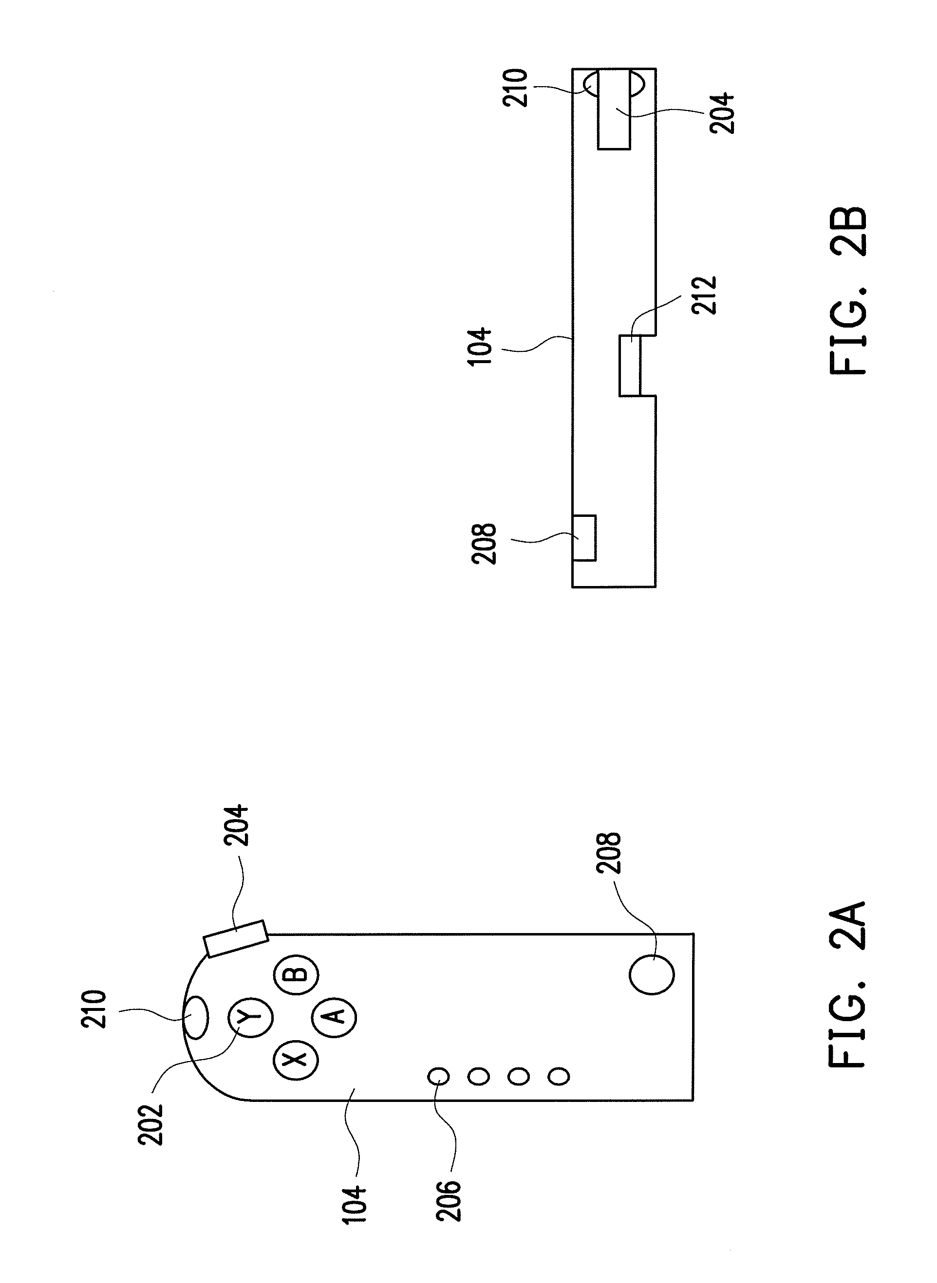
[0048]FIG. 3 is an internal circuit block diagram of a prime motion detector according to a first embodiment of the present invention. Referring to FIG. 3, the prime motion detector 104 includes a micro control unit (MCU) 302, a G-sensor 304, a key-sensing unit 306, a wireless transmitting unit 308, a switch unit 310, an image detection unit 210 and a mouse module 212. In the present embodiment, the G-sensor 304 is an accelerometer. In other embodiment, the G-sensor 304 is for example, a combination of an accelerometer and / or a gyroscope. An input terminal of the switch unit 310 is coupled to output terminals of the image detection unit 210, the G-sensor 304 and the mouse module 212, and an output terminal of the switch unit 310 is coupled to the MCU 302. Moreover, the MCU 302 is coupled to the key-sensing unit 306 and the wireless transmitting unit 308. In the present embodiment, the wireless transmitting unit 308 can be coupled to the receiver 106 via the wireless transmission pat...

second embodiment

[0057]In a second embodiment of the present invention, in the step S512 of FIG. 5, the MCU 302 only judges whether the G-sensing data D1 on a height-axis (z-axis) in the three-dimensional space is within the predetermined range. If the MCU 302 detects the G-sensing data D1 on the height-axis in the three-dimensional space is maintained within the predetermined range, the MCU 302 then confirms that the prime motion detector 104 is only moved on the two-dimensional plane. Now, the MCU 302 can also switch the selection signal SEL to the second state, and the step S516 and so on are executed.

third embodiment

[0058]FIG. 7A and FIG. 7B are side views of a prime motion detector according to a third embodiment of the present invention. FIG. 8 is an internal circuit block diagram of a prime motion detector according to a third embodiment of the present invention. Referring to FIG. 7A and FIG. 8 first, in the present embodiment, the prime motion detector 104 further has a touch switch 702. The touch switch 702 can output the selection signal SEL having a different state to the MCU 302 according to its own state.

[0059]FIG. 9 is a flowchart illustrating a method for generating a detecting data according to a third embodiment of the present invention. Referring to FIG. 8 and FIG. 9, as described in the first embodiment, when the prime motion detector 104 is activated, initialization is performed (S902), and the G-sensor 304, the image detection unit 210 and the key-sensing unit 306 can respectively generate the corresponding G-sensing data D1, the relative position data D2 and the input signal S...


PUM


Abstract

An input apparatus for a computer system comprises an image object, a prime motion detector, and a receiver. The prime motion detector has an image detection unit, a G-sensor, a mouse module, a switch unit, and a micro control unit (MCU). The image detection unit is used for detecting the image object. The switch is coupled to the G-sensor, the image detection unit and the mouse module. By such means, the switch unit can select to transmit an output of the mouse module, or transmit outputs of the G-sensor and the image detection unit to the MCU according to a selection signal. The MCU encodes an output of the switch unit to generate a detecting data to the receiver, and the receiver transmits the detecting data to the computer system for operating the computer system.

Description

CROSS-REFERENCE TO RELATED APPLICATION[0001]This application claims the priority benefit of Taiwan application serial no. 96143773, filed on Nov. 19, 2007. The entirety of the above-mentioned patent application is hereby incorporated by reference herein and made a part of specification.BACKGROUND OF THE INVENTION[0002]1. Field of the Invention[0003]The present invention relates to an input apparatus for a computer system and an operation method thereof. More particularly, the present invention relates to an input apparatus for a computer system and an operation method thereof, in which a mouse operation method is combined.[0004]2. Description of Related Art[0005]A conventional input apparatus for a computer system includes a keyboard, a mouse, a touch panel, etc. Wherein, an input method of the keyboard is to press keys on the keyboard for data inputting, and the mouse and the touch panel are provided for a user to operate the computer system on a two-dimensional plane.[0006]However...

Claims


Application Information

Patent Timeline
IPC IPC(8): G06F3/033
CPCG06F3/0317G06F3/03543G06F3/0346G06F3/0325
Inventor KUO, CHIN-CHUNGPAN, YIH-CHIEHCHANG, LING-CHEN
Owner ASUSTEK COMPUTER INC
Why Eureka
Try Eureka