Method and apparatus for determining a deviation of an actual shape from a desired shape of an optical surface

a technology of optical surface and actual shape, applied in the direction of mirrors, instruments, measurement devices, etc., can solve the problems of difficult prediction, high line densities of diffraction grating with which a grating period is associated, and the rotation averaging method is however only suitable, so as to reduce the remaining errors

Active Publication Date: 2009-05-21
CARL ZEISS SMT GMBH
View PDF29 Cites 39 Cited by
  • Summary
  • Abstract
  • Description
  • Claims
  • Application Information

AI Technical Summary

Benefits of technology

[0057]According to one embodiment of the invention, the diffraction grating is configured such that measuring radiation which is diffracted on the over-grating under a diffraction order different from the zeroth diffraction order has substantially spherical wavefronts. Since this measuring radiation is also diffracted on the grating formed by the adjacent arrangement of the diffraction elements, spherical wavefronts are produced by the combined diffraction of the measuring radiation on the grating and on the over-grating. In this way it is possible to measure and understand the effect of the diffraction grating in a test measurement with the aid of a spherical reference body. In particular, in this way effects of the diffraction grating, which for example can not be described with sufficient precision by a scalar diffraction theory, can be recorded. It can in fact be assumed that the effect of the over-grating can be described relatively well by the scalar diffraction theory upon the basis of its large grating period. If the measuring radiation which should have substantially spherical wavefronts due to the combined effect of the grating and the over-grating, actually has wavefront shapes deviating from the spherical wavefront shape, these deviations can substantially be attributed exclusively to the effect of the grating formed by the adjacent arrangement of the diffraction elements. It is therefore possible to record effects of the grating which deviate for example from a scalar diffraction theory and to take these into account when analysing measurements on an actual measuring object. For this type of measurement measuring radiation is then used which is diffracted on the over-grating under a diffraction order different from the zeroth diffraction order and the

Problems solved by technology

One problem here is that the effect of a diffraction grating with high line densities with which a grating period is not substantially greater than the wave length of the measuring light used is difficult to predict with a simple diffraction theory and moreover production-dependent parameters of the grating, such as for example the base height, edge steepness and the rounding of edges influence the e

Method used


Image

  • Method and apparatus for determining a deviation of an actual shape from a desired shape of an optical surface
  • Method and apparatus for determining a deviation of an actual shape from a desired shape of an optical surface
  • Method and apparatus for determining a deviation of an actual shape from a desired shape of an optical surface

Examples


Embodiment Construction

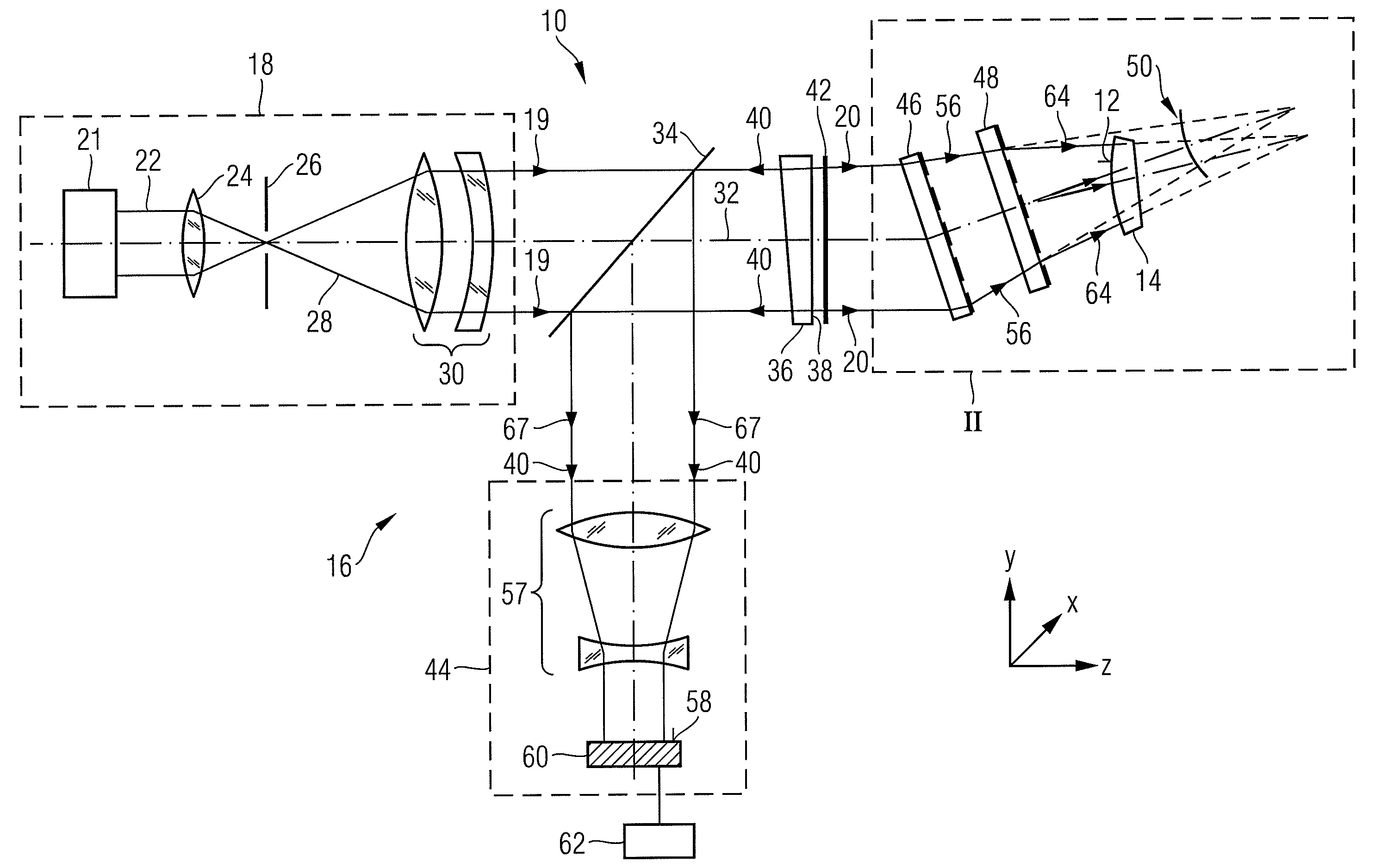
[0097]FIG. 1 illustrates an interferometric measuring apparatus 10 in an embodiment according to the invention. The measuring apparatus 10 is suitable for determining a deviation of an actual shape from a desired shape of an optical surface 12 of a specimen 14. The specimen 14 can for example be in the form of an optical lens or a mirror. The specimen 14 is mounted by means of a holder not shown in the drawings.

[0098]The interferometric measuring apparatus 10 includes an interferometer 16 which in turn includes a light source 18, a beam splitter 34 and an interferometric camera 44. The light source 18 produces illumination radiation 19 and for this purpose includes a laser 21, such as for example a helium-neon laser for producing a laser beam 22. The illumination radiation 19 has sufficient coherent light in order to take an interferometric measurement. In the case of a helium-neon laser, the wave length of the illumination radiation 19 is approximately 634 nm. However, the wave len...


PUM


Abstract

A method of determining a deviation of an actual shape from a desired shape of an optical surface (12; 103) includes: providing an incoming electromagnetic measuring wave (20; 113), providing two diffractive structures (47, 49; 145, 146, 141, 143) which are respectively designed to reshape the wavefront of an arriving wave, calibrating one of the two diffractive structures (47, 49; 145, 146, 141, 143) by radiating the incoming measuring wave (20; 113) onto the at least one diffractive structure to be calibrated (47, 49; 145, 146, 141, 143) and determining a calibration deviation of the actual wavefront from a desired wavefront of the measuring wave (20; 113) after interaction of the latter with the at least one diffractive structure to be calibrated (47, 49; 145, 146, 141, 143), positioning the two diffractive structures (47; 49; 145, 146, 141, 143) in the optical path of the incoming measuring wave (20; 113) such that individual rays of the measuring wave radiate through both diffractive structures (47; 49; 145, 146, 141, 143), and reshaping the incoming measuring wave (20; 113) by means of the two diffractive structures (47; 49; 145, 146, 141, 143) to form an adapted measuring wave (64; 114), the wavefront of which is adapted to the desired shape of the optical surface (12; 103), positioning the optical surface (12; 103) in the optical path of the adapted measuring wave (64, 114) so that the adapted measuring wave (64; 114) interacts with the optical surface (12; 103) and measuring the wavefront of the adapted measuring wave (64; 114) after interaction of the latter with the optical surface (12; 103).

Description

[0001]This application is a continuation-in-part application of international patent application PCT / EP2007 / 006639, filed on Jul. 26, 2007, and claiming priority from German patent application No. DE 10 2006 035 022.7, filed on Jul. 28, 2006. The complete disclosures of these international and priority patent applications are incorporated into this application by reference.FIELD OF AND BACKGROUND OF THE INVENTION[0002]The invention relates to a method and to an apparatus for determining a deviation of an actual shape from a desired shape of an optical surface. Furthermore, the invention relates to a method of producing an optical element. This type of apparatus is described, for example, in WO 2006 / 077145 A2. This apparatus comprises an interferometer for producing a measuring wave, the wavefront of which is hereupon adapted to the desired shape of the optical surface. The wavefront of the adapted measuring wave is analysed interferometrically after reflection on the optical surface...

Claims


Application Information

Patent Timeline
IPC IPC(8): G01B9/02
CPCG01B11/2441G01B9/02039
Inventor SCHILLKE, FRANKFREIMANN, ROLFDREHER, MATTHIAS
Owner CARL ZEISS SMT GMBH
Why Eureka
Try Eureka