Metal halide lamp and lighting device using therewith

Inactive Publication Date: 2009-05-21
HARISON TOSHIBA LIGHTING CORP
View PDF5 Cites 8 Cited by
  • Summary
  • Abstract
  • Description
  • Claims
  • Application Information

AI Technical Summary

Benefits of technology

[0008]According to the present invention, generation of fluctuation can be suppressed for along period in the metal halide lamp having an elec

Problems solved by technology

It is known that there is a problem of flickering in such metal halide lamps containing no mercury.
However, it became clear that preventing flickering for a long period is difficult in metal halide lamp containing no mercury, even when the electrode is doped with thorium oxide.
It is speculated that the thorium oxide is not supplied enough and smoothly during long-term use of the lamp because the electrode temperature becomes so high during lighting that the thorium oxide is accelerated to disappear in lamps containing no mercury.
However, increasing of the thorium oxide tend to turn a color of the light emitting tube into milky, which decreases light flux of the lamp.

Method used


Image

  • Metal halide lamp and lighting device using therewith
  • Metal halide lamp and lighting device using therewith
  • Metal halide lamp and lighting device using therewith

Examples


first embodiment

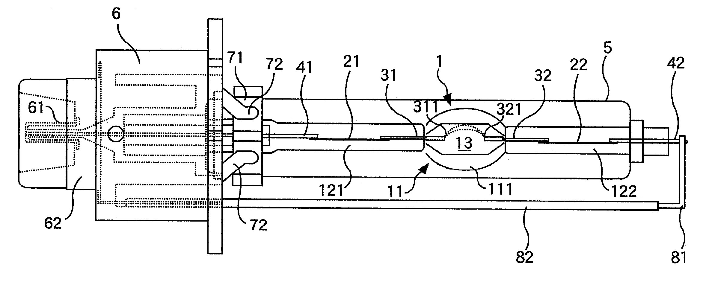
[0021]Hereinafter, a metal halide lamp according to an embodiment of the present invention will be explained referring to the figures. FIG. 1 is a side view showing an overall configuration of a metal halide lamp, which is a first embodiment of the present invention.

[0022]An air tight vessel 1 is made of a material with fire resistance which withstands high temperature during a discharge lamp is lighted and with a translucency which enables generated light to transmit through with as low loss as possible. The vessel 1 is, made of fused quartz, for example. A light emitting tube portion 11 is formed at a nearly central portion of the airtight vessel 1 having a nearly oval sectional shape along the axial direction of the airtight vessel 1. Sealing portions 121, 122 having a plate shape are formed on both ends of the tube portion 11. Inside the light emitting tube portion 11, a discharge space 13 is formed having a nearly cylindrical central portion and taper-shaped ends on both side o...

second embodiment

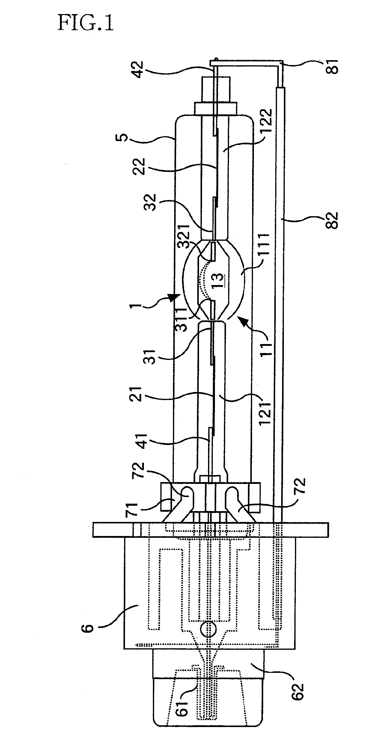
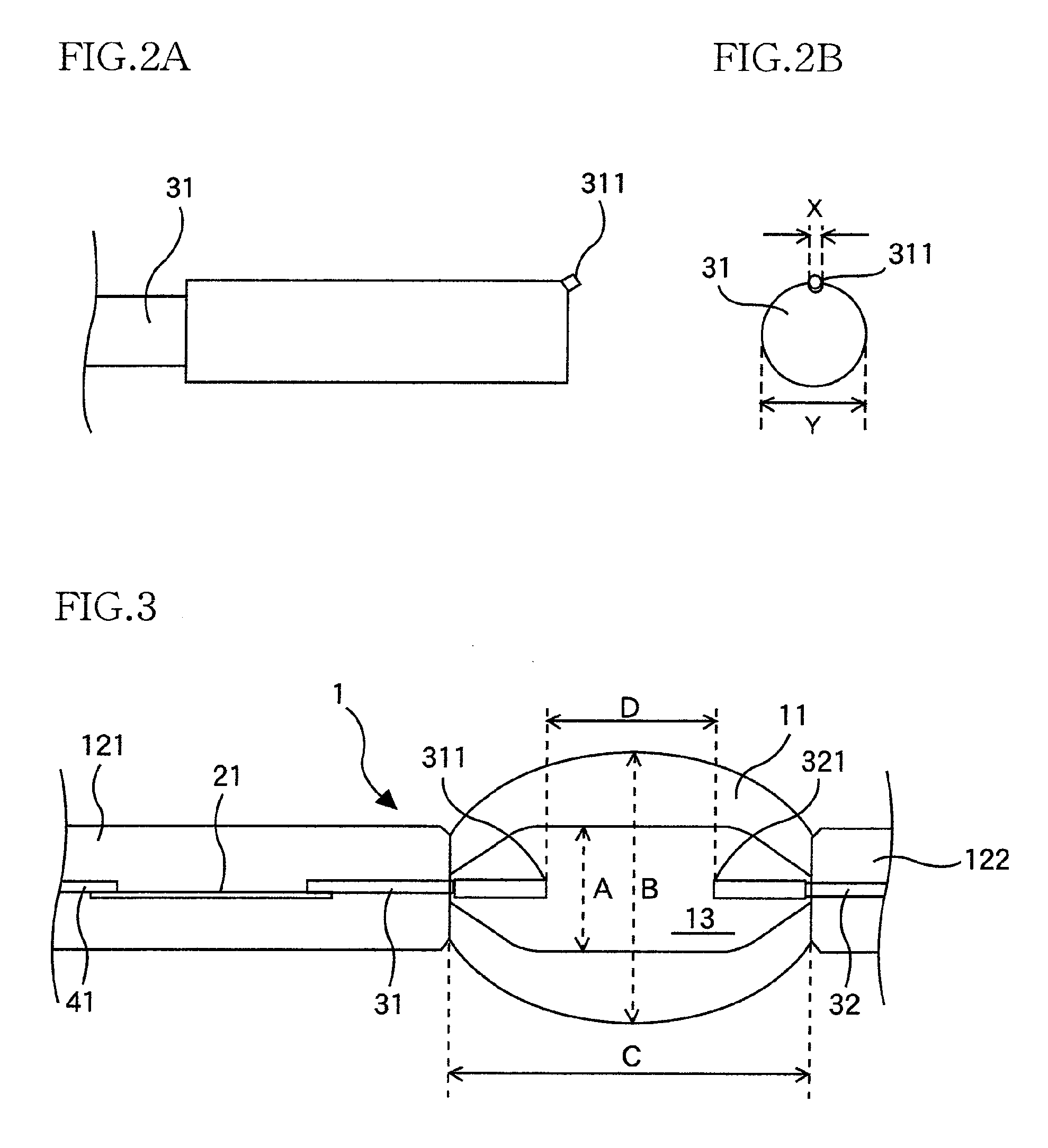
[0061]FIG. 7 is an enlarged view for explaining an electrode according to a second embodiment of the present invention. Same portions with those of the metal halide lamp shown in FIG. 1 are assigned with the same symbols and the explanation is omitted. In the second embodiment, a sharp protrusion 311 (321) is formed on an upper portion of an leading end surface by forming a notch on the upper leading end portion of the electrode 31 (32). Namely, a first protrusion 311 (321) having relatively small size compared with the diameter of the electrode 31 (32) is formed in the leading end portion of the electrode 31 (32) at a position where arc is produced during lighting of the lamp. With even such a protrusion, the similar advantages can be obtained to those described in the description of the first embodiment.

[0062]The first protrusion 311 (321) in the present embodiment is formed by aging with a relatively high electric power of 75 W or more supplied from the lighting circuit. The dime...

third embodiment

[0064]FIG. 8A and FIG. 8B are enlarged views for showing an electrode according to a third embodiment of the present invention. In the figures, same portions of the metal halide lamp as those shown in FIG. 1 are assigned with the same symbols and the explanation is omitted. In the third embodiment, a second protrusion 312, (322) is formed on a lower portion of electrode 31, (32), in addition to the first protrusion 311, (321), formed on an upper portion of the electrode.

[0065]FIG. 9 is a table listing a good-quality rate relating to the flickering in the life period with the protrusion on a top and a bottom portion of the electrode of the metal halide lamp according to the lamp specification shown in FIG. 3. For the comparison purpose, tests were performed using samples with protrusions on the top and the bottom of one of a pair of electrodes, samples with protrusions on the top and the bottom of both electrodes, and samples with no protrusions. The test conditions etc. are similar ...


PUM


Abstract

A metal halide lamp comprises a translucent air tight vessel (1) having an arc tube section (11) forming a discharge space (13) and sealing portions (121, 122) formed at the both ends thereof, a discharge medium with which the discharge space is filled, and a pair of electrodes (31, 32) projecting into the discharge space. The discharge medium is composed of a metal halide and rare gas and essentially containing no mercury. The pair of the electrodes is composed of tungsten containing thorium oxide. Protrusions (311, 312) are formed respectively, on the pair of electrodes and arc is formed between them when the metal halide lamp is operated.

Description

TECHNICAL FIELD[0001]The present invention relates to metal halide lamp used for headlights of motorcars or the like and to lighting device using the metal halide lamps.BACKGROUND TECHNOLOGY[0002]Metal halide lamp enclosing no mercury is known and is disclosed in Japanese Unexamined Patent Application Publication No. 2005-142072. The lamp is provided with an airtight vessel having a discharge space of 0.1 cc or less and sealing portions on the both ends. The lamp is also provided with a pair of electrodes each of which has nearly column-shaped end portion and nearly column-shaped shaft portion formed on the end portion, wherein the diameter R (mm) of the end portion is 0.30≦R≦0.40, wherein the diameter r (mm) of the shaft portion is 0.25≦r≦0.30, and wherein R>r, The end portions are arranged and sealed at the sealing portion so as to face each other by an inter electrode distance of 5 mm or less in the discharge space of the air tight vessel. A discharge medium containing metal h...

Claims


Application Information

Patent Timeline
IPC IPC(8): F21V15/01H01J17/04
CPCH01J61/827H01J61/0732
Inventor WAJATA, TAKAYUKI
Owner HARISON TOSHIBA LIGHTING CORP
Why Eureka
Try Eureka