Probe cover for ear thermometer and manufacturing method thereof

a technology of ear thermometer and manufacturing method, which is applied in the direction of heat measurement, optical radiation measurement, instruments, etc., can solve the problems of relative large ejection force required for forced demoulding, disadvantage in view of ergonomics, and relatively difficult manufacturing, so as to facilitate manufacturing and save processing time , the effect of enhancing the lifetim

Inactive Publication Date: 2009-05-21
ACTHERM INC
View PDF20 Cites 31 Cited by
  • Summary
  • Abstract
  • Description
  • Claims
  • Application Information

AI Technical Summary

Benefits of technology

[0008]It is another objective of the present invention to provide a probe cover for an ear thermometer having a plurality of protuberances, wherein a smaller ejection force for demoulding the probe cover out of a mold than that required by a conventional probe cover having an annular groove so as to facilitate manufacturing and therefore saving processing time.
[0009]It is still another objective of the present invention to provide a probe

Problems solved by technology

Such probe cover of the multi-component type requires relatively complex processing procedures and may have intervals at joints between combined components that bring discomfort to human ears, thereby being disadvantageous in view of ergonomics.
The first problem is that during manufacturing such probe covers, the annular groove can tightly cover the mould, and thereby a relative large ejection force is required for forced demoulding.
Thus, the manufacturing is relatively difficult and the overall processing time can be significantly increased.
Therefore, when the probe cover is assembled to or disassembled fro

Method used


Image

  • Probe cover for ear thermometer and manufacturing method thereof
  • Probe cover for ear thermometer and manufacturing method thereof
  • Probe cover for ear thermometer and manufacturing method thereof

Examples


Embodiment Construction

[0018]While the present invention discloses a probe cover for an ear thermometer and a manufacturing method thereof, it is to be stated first of all that the basic principle where the ear thermometer operates upon have been familiar to people skilled in the art and need not be discussed at length herein. Meantime, while the accompanying drawings are provided for the purpose of illustration, it is to be understood that the drawings are directed to the characteristics of the present invention and need not to be made in scale.

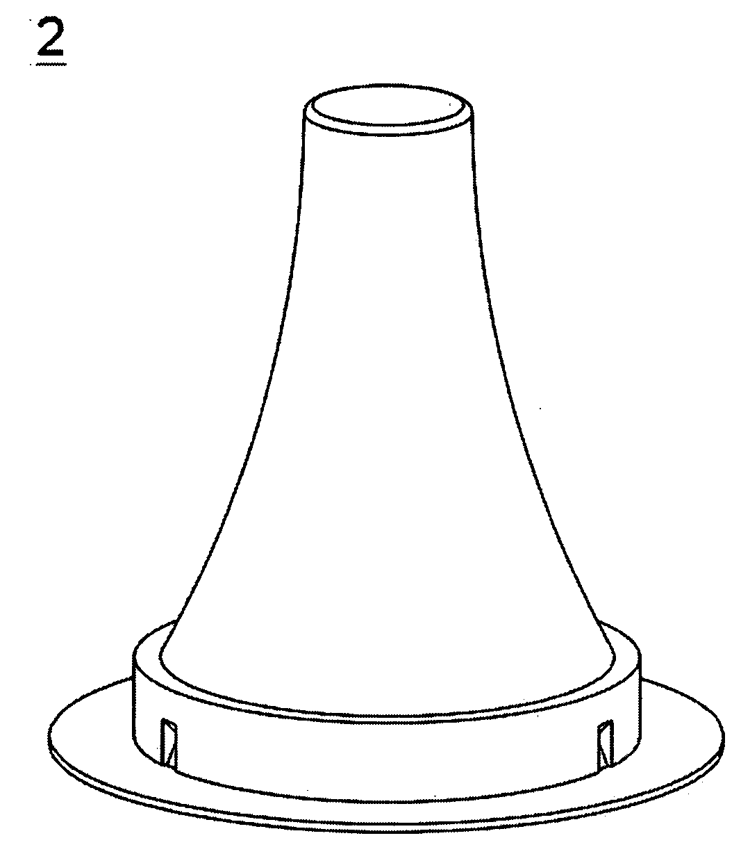
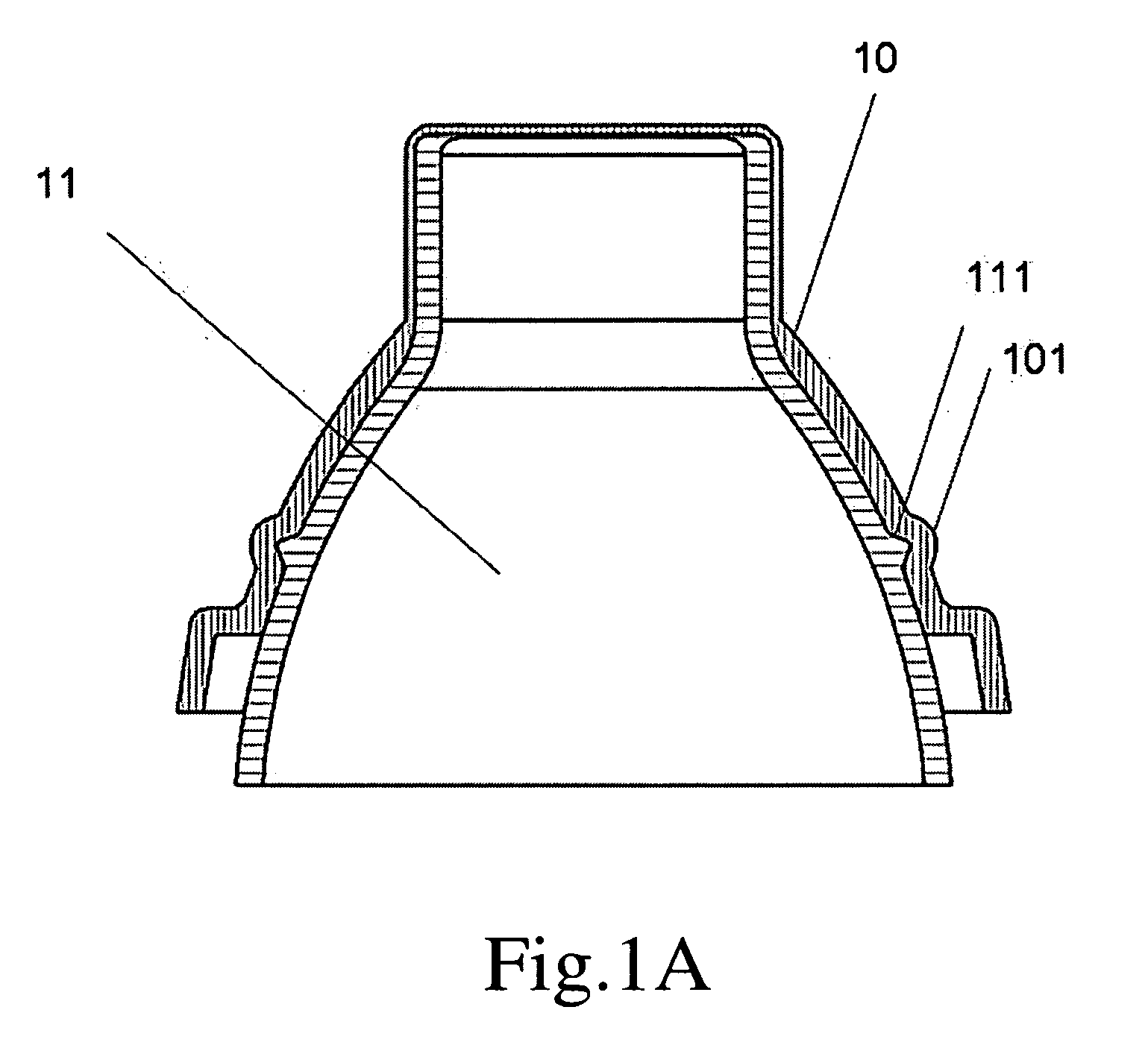
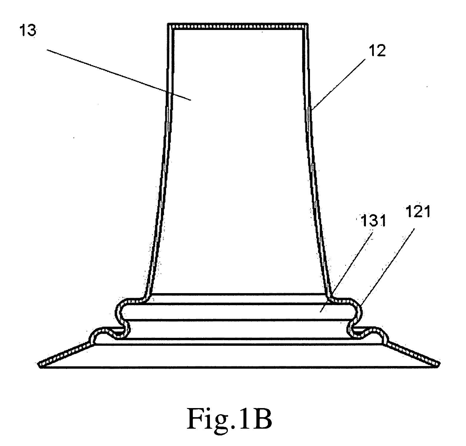
[0019]Please refer to FIGS. 2A to 2E for a first embodiment of the present invention. Therein, a probe cover 2 for an ear thermometer has a main body 23 of a hollow structure, an abutting segment 24 and a base 25 for sheathing a measuring probe 201 of the ear thermometer 20. Further, an engaging means 202 is provided at a bottom of the measuring probe 201.

[0020]The engaging means 202 may be shaped as an annulation, a dot or a block while the engaging means 202 is ...


PUM

PropertyMeasurementUnit
Forceaaaaaaaaaa
Angleaaaaaaaaaa
Shapeaaaaaaaaaa

Abstract

The present invention provides a probe cover for an ear thermometer and a manufacturing method thereof. The probe cover is for sheathing a measuring probe of the ear thermometer, and an engaging means is provided at a bottom of the measuring probe. The probe cover comprises a main body of a hollow structure, an abutting segment and a base. Therein, the main body has an open end and a closed end opposite to the open end. An assembling direction extending from the open end toward the closed end is where the measuring probe is assembled along. Further, the main body has a diameter gradually reducing along the assembling direction. The closed end allows infrared rays to be received by the measuring probe to pass therethrough. Therein, the abutting segment is provided at the open end of the main body, and the base is annularly provided around a periphery of the abutting segment. The probe cover is characterized in being integrally formed, and having an annular shoulder provided at the abutting segment for accommodating the engaging means of the ear thermometer, as well as a plurality of separated protuberances, which are formed inwardly at a combining portion between the abutting segment and the base, for being engaged with the engaging means of the ear thermometer so that the probe cover can be firmly engaged with the measuring probe.

Description

BACKGROUND OF THE INVENTION[0001]1. Technical Field[0002]The present invention relates to a probe cover for an ear thermometer and a manufacturing method thereof. More particularly, the present invention relates to a probe cover for an ear thermometer having protuberances provided at a combining portion between an abutting segment and a base for coupling with an engaging means of the ear thermometer.[0003]2. Description of Related Art[0004]The know probe cover for an ear thermometer may be of a multi-component type, such as the one disclosed in U.S. Pat. No. 4,911,559. Such probe cover of the multi-component type requires relatively complex processing procedures and may have intervals at joints between combined components that bring discomfort to human ears, thereby being disadvantageous in view of ergonomics. To remedy the above problems, U.S. Pat. No. 5,088,834 disclosed a unitary probe cover 10. Further, for ensuring firm combination between the probe cover 10 and a measuring pro...

Claims


Application Information

Patent Timeline
IPC IPC(8): G01K1/08
CPCG01J5/02Y10T29/49G01J5/021
Inventor CHUANG, LI-HENGLI, LIANG-YI
Owner ACTHERM INC
Why Eureka
Try Eureka