Parting method for fragile material substrate and parting device using the method

a technology of fragile material and parting device, which is applied in the direction of conveyors, manufacturing tools, paper/cardboard containers, etc., can solve the problems of difficult to completely remove the cullet, damage to the quality of flat display panels, and unavoidable production of chips (cullets) in the scribing process, and achieve stable scribing and good quality scribe lines

Inactive Publication Date: 2005-11-03
MITSUBOSHI DIAMOND IND CO LTD
View PDF19 Cites 22 Cited by
  • Summary
  • Abstract
  • Description
  • Claims
  • Application Information

AI Technical Summary

Benefits of technology

[0059] In this way, a cutter wheel 21 provided with projections 81 is able to obtain a long vertical crack with a depth proportional to the applied load, while producing little horizontal cracks even when the blade-edge pressure is large. With a long vertical crack, precise breaking can be performed along the scribe line in the breaking operation of the subsequent step, thus improving yield. Furthermore, as the breaking operation is made easier, the requirements of the device configurations used in the breaking process can be relaxed or simplified, and depending on the situation it is also possible to eliminate the breaking process.
[0064] The cutter wheel shown in FIG. 23 is provided with grooves along the entire periphery of the cutter wheel, and the use of this cutter wheel is advantageous in that a vertical crack produced at the same time of inscribing a scribe line that extends from that scribe line is produced as a long crack that almost passes through the glass substrate in the thickness direction via the thin film and the protective coating.
[0066] The second cutter wheel 40 is formed by an area Y in which grooves 6b are formed at the blade-edge ridge portion, and an area N in which no groove is formed. The cutter wheel 40 can save processing time for forming grooves 6b, and has superior workability.
[0069] The use of these cutter wheels makes it possible to perform severing in accordance with the material of the brittle material substrate. Furthermore, the use of the first cutter wheel can achieve a vertical crack that reaches the lower surface of the glass substrate. On the other hand, the use of the second cutter wheel can produce a vertical crack in which the depth is periodically varied.
[0074] With the use of the scribe heads using the servomotor, the rotational torque of the servomotor is immediately corrected in response to a change in the scribe pressure resulting from the fluctuation in the resistance force exerted on the cutter wheel when scribing is performed through the protective material such as a coating or a film; accordingly, it is possible to perform stable scribing, thus forming a good quality scribe line.

Problems solved by technology

Whether few or many in number, chips (cullets) are unavoidably produced in the scribing process.
The bonded brittle material substrate that has undergone the severing processes or the brittle material substrate that has been bonded after the severing are used as, for example, organic EL devices or liquid crystal display panels; however, when such cullets remain on the substrates during the severing process, abrasion can be caused to the substrates, thus becoming a cause of damage to the quality of flat display panels.
However, operations to remove the cullets produced in scribing are troublesome, and moreover, it is very difficult to completely remove the cullets.
When the cullets remain in the periphery of the devices used for the severing process, there is the problem that the surface of the glass substrate may be scratched by the cullets.
Such scratching is not desirable for a liquid crystal display substrate, and especially for projector substrates, strict quality control is required.
Once scratches are caused on the glass substrate, its quality as a projector substrate is reduced significantly and thus reliability cannot be ensured, resulting in a reduced yield.

Method used


Image

  • Parting method for fragile material substrate and parting device using the method
  • Parting method for fragile material substrate and parting device using the method
  • Parting method for fragile material substrate and parting device using the method

Examples


first embodiment

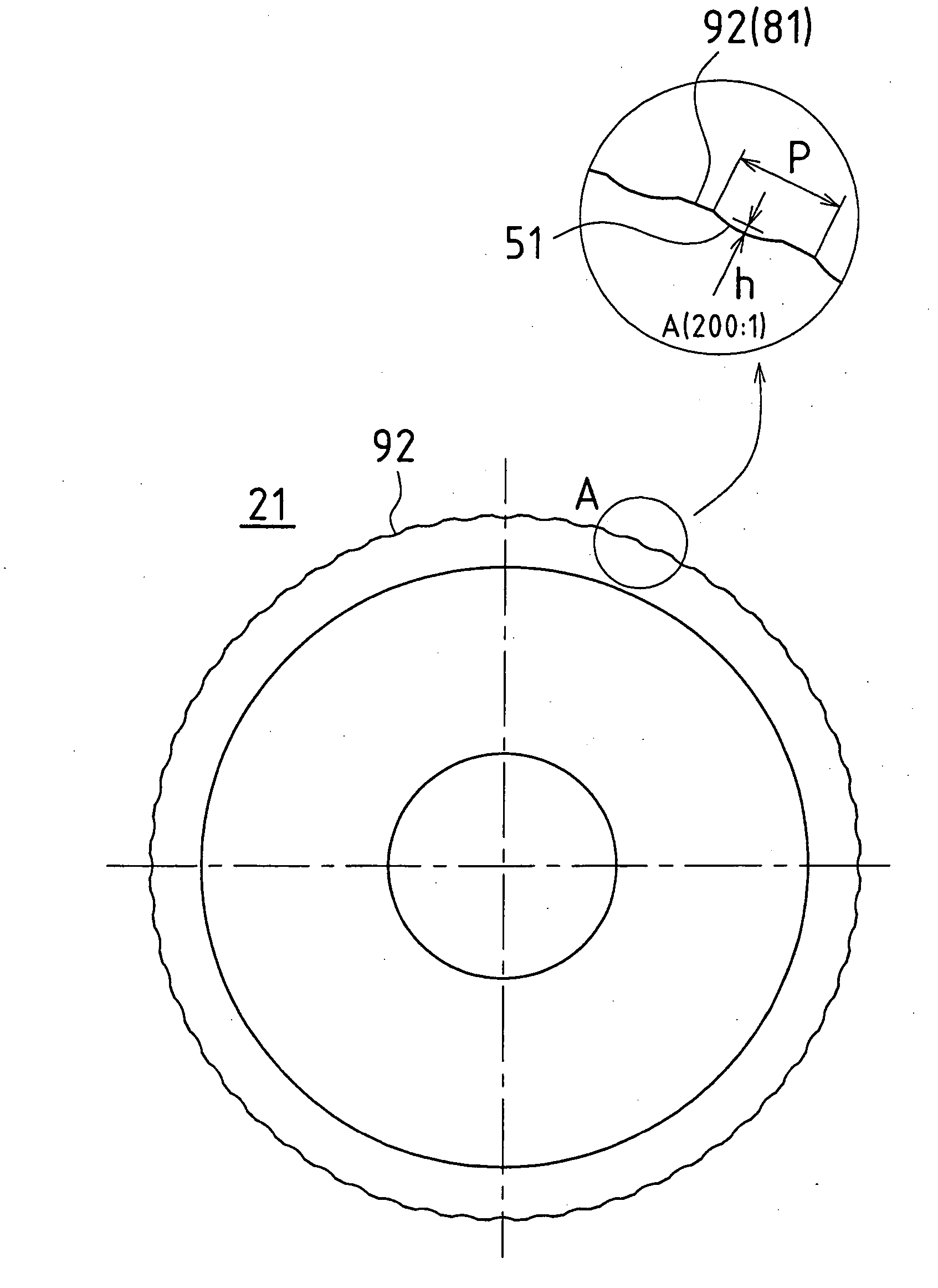
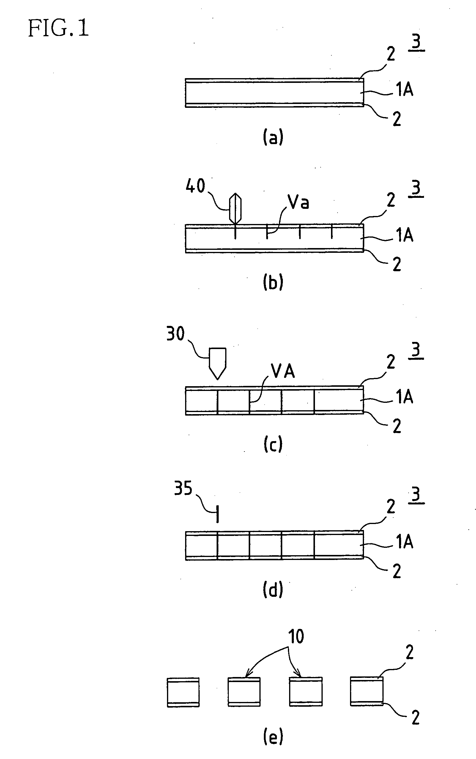
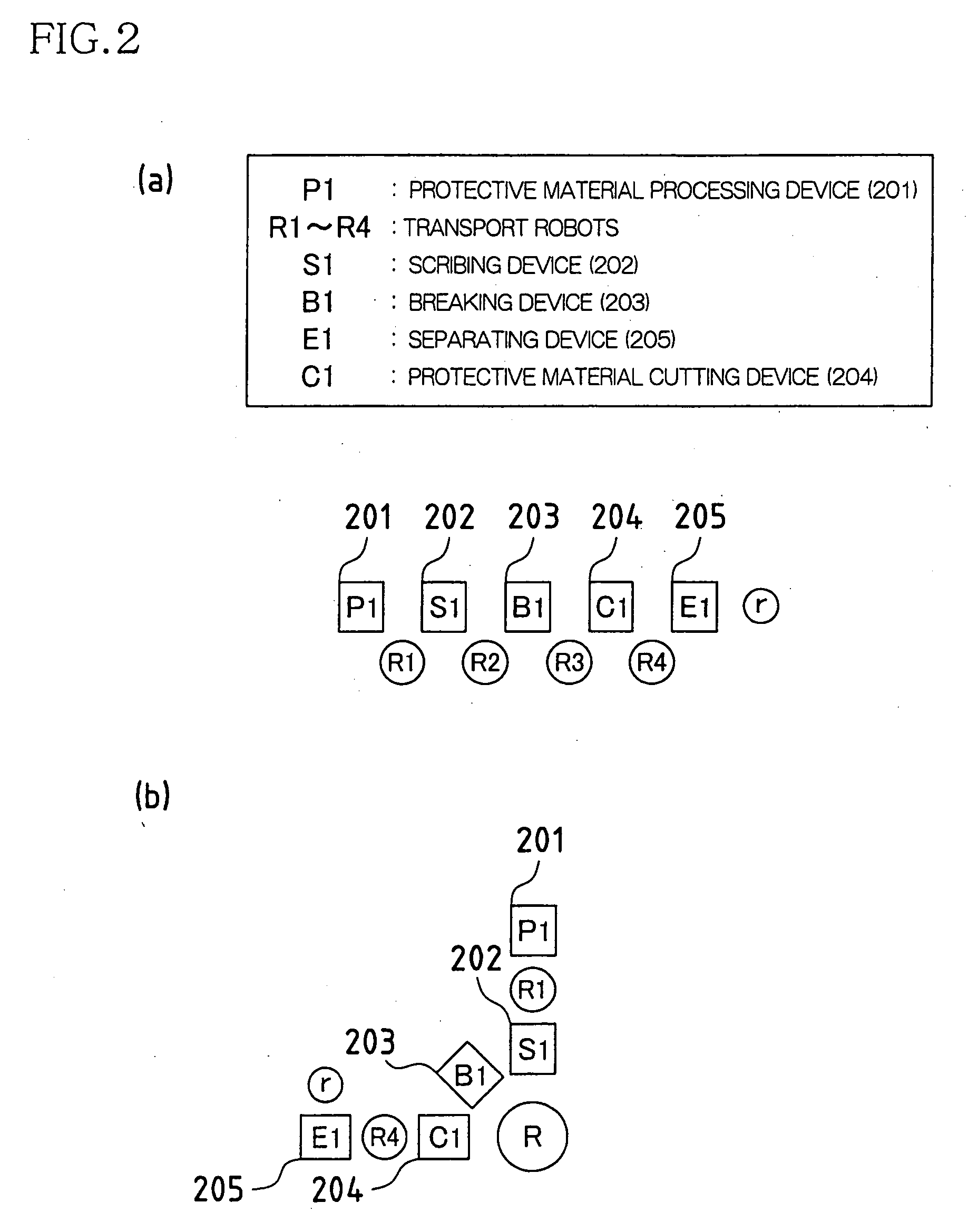
[0108] FIGS. 1(a) to (e) are process diagrams for illustrating a first embodiment of the present invention. FIG. 2 includes diagrams schematically showing a configuration of the devices used in such a process. FIG. 2(a) shows an example in which the devices of the process are configured in a simplified line. FIG. 2(b) is an example in which the devices are configured around a transport robot R. The present invention is applied to a process of severing a single-plate brittle material substrate 3, which is one kind of a brittle material substrate. The single-plate brittle material substrate 3 is a glass substrate 1A, and the material of the glass is a non-alkali glass, for example. Furthermore, the cutter wheel used is the second cutter wheel 40 shown in FIG. 25 that can achieve a vertical crack with periodically varied depths in a glass substrate.

[0109] (1) First, a protective material processing device 201 is provided with the same mechanisms as the film application mechanisms used...

second embodiment

[0123] FIGS. 3(a) to (d) are process diagrams for illustrating a second embodiment of the present invention. FIG. 4 includes diagrams schematically showing a configuration of the devices used in such a process. FIG. 4(a) shows an example in which the devices of the process are configured in a simplified line. FIG. 4(b) is an example in which the devices are configured around a transport robot R. The present invention is applied to a process of severing a single-plate brittle material substrate 3, which is one kind of a brittle material substrate. The single-plate brittle material substrate 3 is a semiconductor wafer, and the material of the semiconductor wafer is a silicon substrate 1C, for example. The silicon substrate 1C is a combination of a glass and a semiconductor wafer, and used as a substrate for reflective-type projectors and the like. In the case of the substrate for reflective-type projectors, a projected light passes through the glass substrate and is reflected on the r...

third embodiment

[0137] FIGS. 5(a) to (h) are process diagrams for illustrating a third embodiment of the present invention. FIG. 6 includes diagrams schematically showing a configuration of the devices used in such a process. FIG. 6(a) shows an example in which the devices of the process are configured in a simplified line. FIG. 6(b) is an example in which the devices are configured around a transport robot R. The present invention is applied to a process of severing a single-plate brittle material substrate 3, which is one kind of a brittle material substrate. The single-plate brittle material substrate 3 is a glass substrate 1A, and the material of the glass is a non-alkali glass, for example. Furthermore, the cutter wheel used is the second cutter wheel 40 shown in FIG. 25 that can produce a vertical crack with periodically varied depths in a glass substrate.

[0138] (1) First, a protective material processing device 261 is provided with the same mechanisms as the film application mechanisms used...


PUM

PropertyMeasurementUnit
lengthaaaaaaaaaa
thicknessaaaaaaaaaa
inner diameteraaaaaaaaaa

Abstract

There are provided a scribing step of performing scribing in a state in which a protective material is applied on at least one surface of a brittle material substrate, and a first scribing device that performs this scribing step. Accordingly, it is possible to form a vertical crack that reaches deep inside of the substrate, while effectively removing cullets produced at the time of severing the substrate, thus performing precise severing along a scribe line.

Description

TECHNICAL FIELD [0001] The present invention relates to methods for scribing and breaking bonded brittle material substrates that are formed by bonding brittle material substrates and used for various flat display panels, and pre-bonded, single-plate brittle material substrates, as well as to severing apparatuses for the brittle material substrates using such methods. Terminology ‘severing’ is used throughout the specification to denote either ‘scribing and breaking’ or ‘breaking process after scribing process.’BACKGROUND ART [0002] Products related to the flat display panels, such as liquid crystal display panels, organic EL devices and liquid crystal projector substrates have been used as means for transmitting information between machines and human beings in various applications. The bonded brittle material substrates used for such flat display panel-related products have a configuration in which two substrates with various electronic control circuit means and the like required f...

Claims


Application Information

Patent Timeline
Patent Type & Authority Applications(United States)
IPC IPC(8): B28D5/00C03B33/033C03B33/07C03B33/10
CPCB28D5/0011B65G2249/04C03B33/107C03B33/074C03B33/10C03B33/033Y10T83/0333Y10T83/0385Y02P40/57B28D5/00C03B33/023
Inventor MAEKAWA, KAZUYASOYAMA, HIROSHI
Owner MITSUBOSHI DIAMOND IND CO LTD
Why Eureka
Try Eureka