Equalizer circuit

Active Publication Date: 2009-05-21
LAPIS SEMICON CO LTD
View PDF1 Cites 6 Cited by
  • Summary
  • Abstract
  • Description
  • Claims
  • Application Information

AI Technical Summary

Problems solved by technology

Consequently, noise components included in the sub-carrier of pilot symbols pass through the filter, and spread to neighboring channels, and then an error in propagation-path estimation occurs.
However, since there is a difference between the propagation-path characteristics received by the past OFDM symbols and the propagation-path characteristics received by the current OFDM symbol in the circumstances where the propagation-path state is changed rapidly, the above error in propagation-path estimation can become rather large.
Since the delay time calculated by the above method is not a real delay time and is calculated based on discrete time used in digital signal processing, there is an error in the delay time, and a plurality of complex gains occurs at a plurality of delay times as errors.
Subsequently, the error in propagation-path estimation becomes larger.
Additionally, the conventional method calculates complex gains and delay times in the number of detectable delay paths.
Consequently, repeating times more than the number of delay paths necessary to be detected becomes necessary, and then calculation amount becomes very large.
Furthermore, since the number of delay paths in a real transmission cannot be already known, largish repeating time is necessary to be used.
However, according to the propagation-path estimation apparatus described in Japanese Patent Application Laid-Open Publication No. 2006-262039, there is a problem as follows, too.
Consequently, the precision of the estimation becomes lower and the received signal cannot be demodulated stably.

Method used


Image

  • Equalizer circuit
  • Equalizer circuit
  • Equalizer circuit

Examples


first embodiment

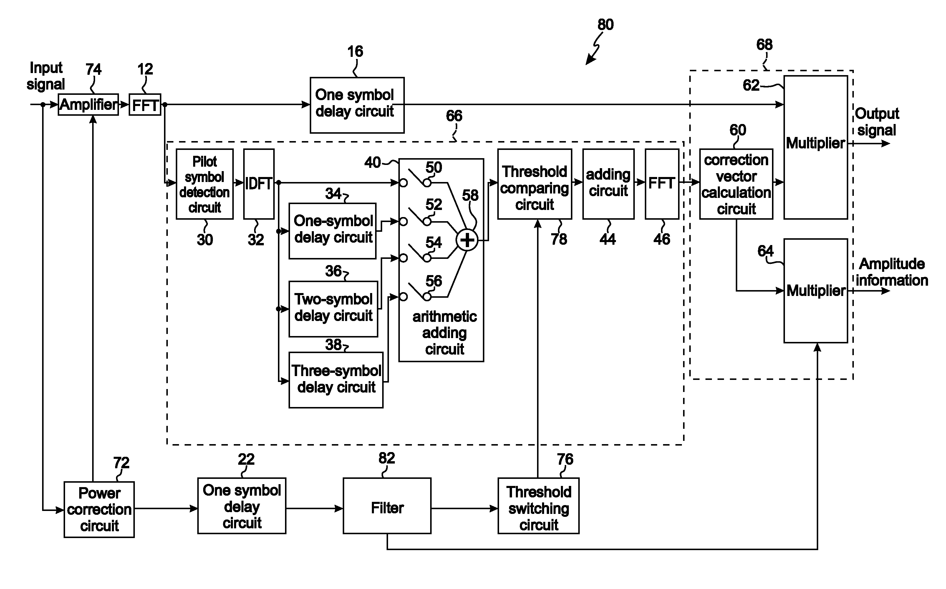
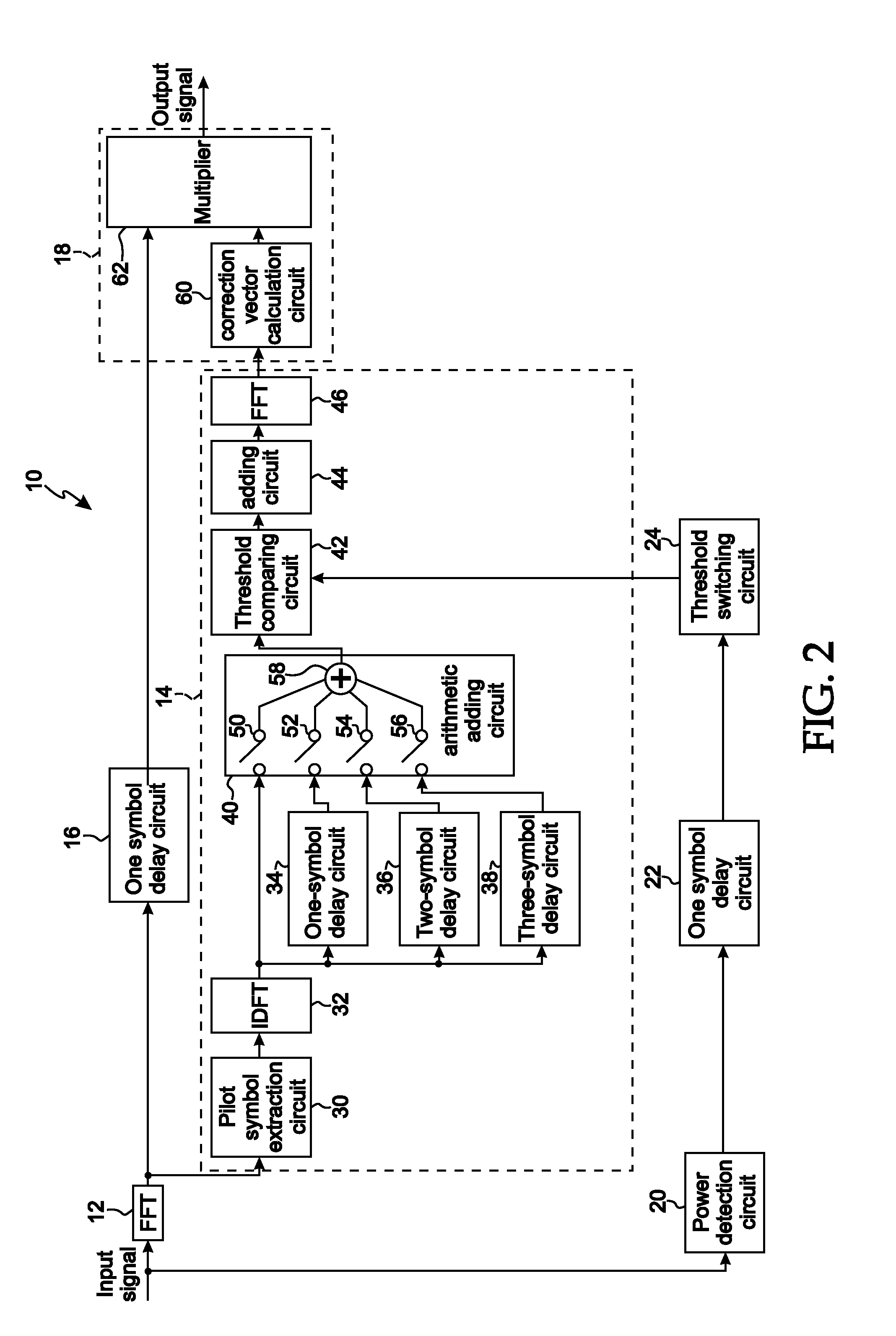
[0054]In addition, the threshold calculation coefficient Pf_th (t) is calculated by the power detection circuit 20 and the threshold switching circuit 24.

[0055]The OFDM signal before being Fourier transformed by the fast Fourier transform circuit 12 is an input of the power detection circuit 20. The power detection circuit 20 detects the power in the received signal corresponding to one-symbol of the OFDM signal. As methods for detecting the power, various methods can be used. As one of the power detection circuit 20, a current detecting circuit having voltage output function and a multiplier can be installed so as to detect the power by multiplying a voltage proportional to the current detected by the current detecting circuit and a voltage of the input OFDM signal by the multiplier.

[0056]The one-symbol delay circuit 22 is placed on the subsequent stage of the power detection circuit 20. The one-symbol delay circuit 22 delays the detected power value from the power detection circu...

second embodiment

[0090]Consequently, in the case where the output from the power correction circuit 72 is smaller, the relative threshold becomes smaller, and in the case where the output from the power correction circuit 72 is larger, the relative threshold becomes larger. In other words, in the case where the output from the power correction circuit 72 is smaller, since the ratio of the unnecessary power such as noise, etc. is smaller, the precision of the propagation-path estimation is improved by heightening the relative threshold, and in the case where the output from the power correction circuit 72 is larger, since the ratio of the unnecessary power is larger, the complex gains generated by noise thereof is eliminated by lowering the relative threshold.

[0091]In addition, according to the second embodiment, it is configured that three kinds of the threshold calculation coefficients is settable, however, it is possible to configure that other threshold calculation coefficients than the three ki...


PUM


Abstract

In an equalizer circuit of one aspect, a first Fourier transform circuit Fourier-transforms an input signal and outputs a corresponding first Fourier-transformed signal, and a first extracting circuit extracts a plurality of pilot symbols from the first Fourier-transformed signal. An inverse Fourier transform circuit calculates a complex gain of each path of the input signal by inverse-transforming the plurality of pilot symbols extracted by the first extracting circuit. A detecting circuit detects at least one of a power value and a mean amplitude of the input signal, and a coefficient determining circuit determines a coefficient corresponding to the at least one of the power value and the mean amplitude detected by the detecting circuit. A second extracting circuit extracts complex gains having a power larger than a threshold obtained by multiplying the coefficient determined by the coefficient determining circuit by a value obtained by integrating the power for a period of time, wherein the power is obtained from the complex gains of each path of the input signal calculated by the inverse Fourier transform circuit. A second Fourier transform circuit Fourier-transforms the extracted complex gains from the second extracting circuit to obtain a corresponding second Fourier-transformed signal, and an equalizing calculation circuit equalizes the input signal using the second Fourier-transformed signal.

Description

BACKGROUND OF THE INVENTION[0001]1. Field of the Invention[0002]The present invention generally relates to the demodulation of OFDM (Orthogonal Frequency Division Multiplexing) digital modulated signals, and more particularly, the present invention relates to an equalizer which may be utilized in the demodulation of OFDM digital modulated signals.[0003]A claim of priority is made to Japanese patent application no. 2007-262150, filed Oct. 5, 2007, the entirety of which is incorporated herein by reference.[0004]2. Description of Related Art[0005]In broadcasting systems, such as terrestrial digital broadcasting (ISDB-T), OFDM modulation techniques have been adopted in view of their relative immunity to multi-path interference. In OFDM modulation, a scattered pilot method may be utilized in which modulation is executed by scattering pilot symbols along frequency and time directions as amplitude and phase references in the data symbols, and demodulation is executed by estimating propagat...

Claims


Application Information

Patent Timeline
IPC IPC(8): H04L27/01
CPCH04B3/143H04L25/0212H04L2027/0024H04L27/2647H04L25/03159
Inventor AKAHORI, HIROJI
Owner LAPIS SEMICON CO LTD
Why Eureka
Try Eureka