Eureka AIR delivers breakthrough ideas for toughest innovation challenges, trusted by R&D personnel around the world.

Device for maintaining a hydraulic turbomachine

Active Publication Date: 2009-05-21
ELECTRICITE DE FRANCE
View PDF8 Cites 11 Cited by
  • Summary
  • Abstract
  • Description
  • Claims
  • Application Information

AI Technical Summary

Benefits of technology

[0017]According to an embodiment of the present invention, at least one post portion is surrounded with a stiffening sleeve having, in a plane perpendicular to the axis of the drive shaft, a wing profile to limit the drag.

Problems solved by technology

Thereby, a breakage of a blade of a single turbine unit may cause the failure of the turbine unit.
However, this complicates the column design and manufacturing.
In this case, the turbine units remote from the generator are oversized in thickness with respect to the torsion torque that they actually receive, which degrades the hydrodynamic performances of the column.
The installation cost of such a column group is very high.
Such operations are thus relatively expensive, technically difficult, and require for divers to take significant risks due to the marine current present at the column level.
However, the tension forces necessary for an efficient stiffening of the turbomachine drive shaft increase very rapidly along with the drive shaft length.
Further, mechanical stress that may be excessive may develop at the turbomachine drive shaft and at the devices for holding in position the ends of the turbomachine.
It is accordingly difficult to avoid a strong bend of the drive shaft, which adversely affects a proper rotation of the turbomachine drive axis in the marine or river current.
Further, the use of barges holding in position the upper end of the turbomachine may be incompatible with the circulation of boats, in particular in the case where the turbomachine is arranged in a stream bed or in the presence of a strong swell.
Indeed, in this last case, the system for anchoring the barge to the sea bottom, to a stream bed or to a bank, etc. may be under excessive stress and vertical oscillations of the barge may result in interactions which are difficult to control between the barge and the turbomachine.

Method used


Image

  • Device for maintaining a hydraulic turbomachine
  • Device for maintaining a hydraulic turbomachine
  • Device for maintaining a hydraulic turbomachine

Examples


first embodiment

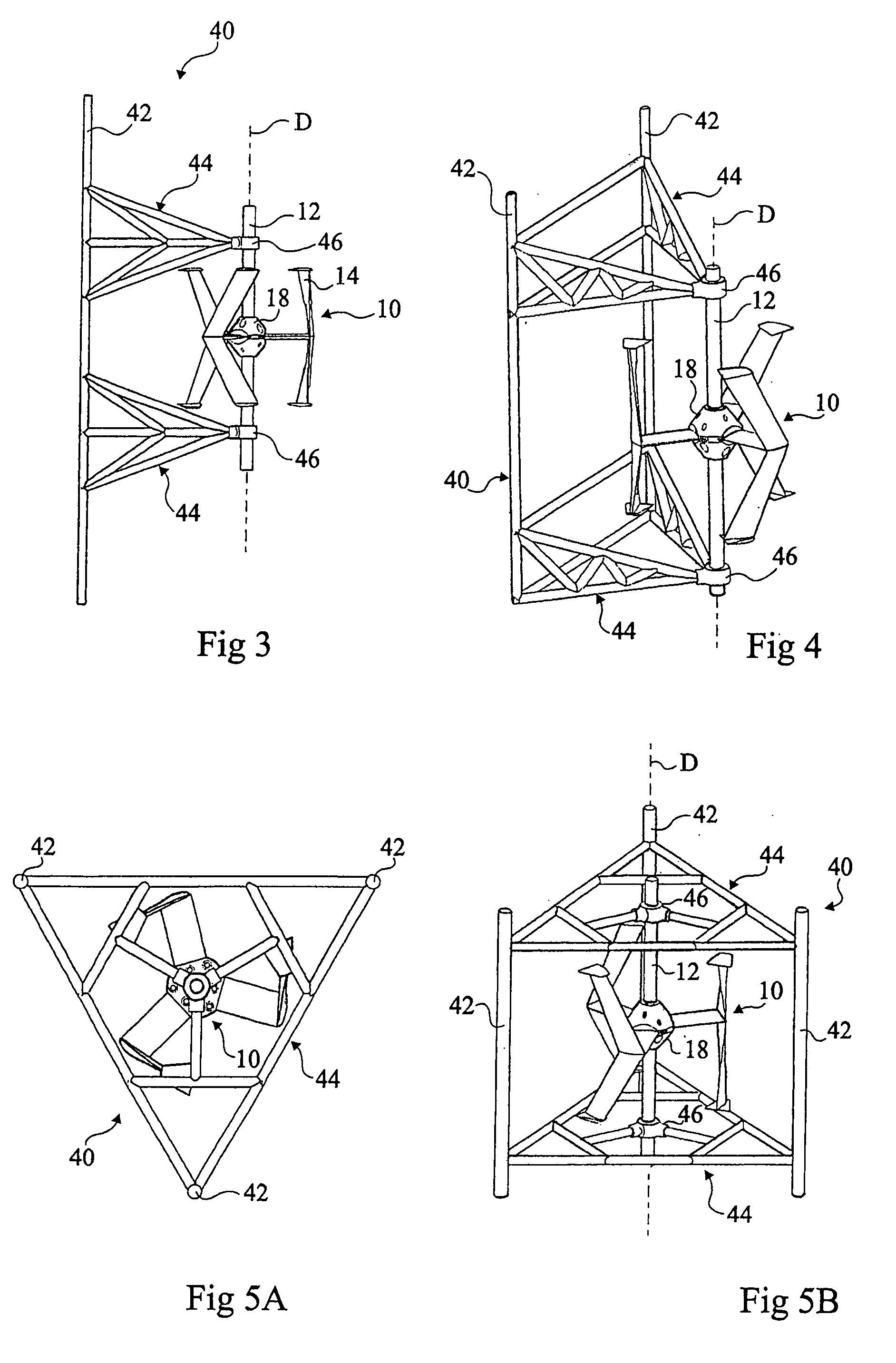
[0065]FIG. 3 shows a structure unit 40 ensuring the holding of a turbine unit 10. Structure unit 40 comprises a post 42 oriented along axis D and linking means 44 connecting post 42 to bearings 46 arranged on either side of hub 18 of turbine unit 10 and in which drive shaft portion 12 of turbine unit 10 is rotatably mounted. Direction D generally corresponding to the vertical direction, post 42 will be called a vertical post hereafter. Vertical post 42 may be a hollow beam with a circular cross-section or shaped as a wing profile. Linking means 44 generally extend along a direction perpendicular to axis D, and comprise, in the present embodiment, an assembly of beams arranged in a lattice.

second embodiment

[0066]FIG. 4 shows a second embodiment in which structure unit 40 comprises two vertical posts 42 connected by linking means 44 to two bearings 46 receiving drive shaft portion 12 of turbine unit 10 on either side of hub 18. Linking means 44 are formed of beams arranged in a lattice and comprise beams 48 which connect vertical posts 42 to each other to stiffen structure unit 40.

[0067]For the first and second embodiments, structure units 44 are advantageously arranged in operation in the marine or river current downstream of turbine unit 10 along the current flow direction. They thus enable positioning the associated turbine unit 10 in an upstream region without forming an obstacle for the current.

third embodiment

[0068]FIGS. 5A and 5B show a third embodiment in which structure unit 40 comprises three vertical posts 42 arranged, as seen from above, at the apices of a triangle, for example, an equilateral triangle. Vertical posts 42 are connected by linking means 44 to two bearings 46 receiving drive shaft portion 12 of turbine unit 10 on either side of hub 18. Linking means 44 are formed of beams arranged in a lattice which also connect posts 42 to one another to stiffen structure unit 40.


PUM


Abstract

A device for holding a hydraulic turbomachine in position, the turbomachine comprising a drive shaft along which are distributed turbines designed to rotate the drive shaft when they are immersed in a moving liquid, each turbine comprising drive blades distributed around the drive shaft, the device comprising at least one post extending along at least more than half of the length of the drive shaft and formed of the stacking of at least two post portions, each Post portion being associated with a turbine or with an assembly of adjacent turbines; and a first linking mechanism attached to one of the post portions and to a bearing receiving the drive shaft and arranged between two adjacent turbines; and a second linking mechanism connecting at least one of the posts to the around by a rigid connection with respect to the ground along at least one axis parallel to the liquid motion direction.

Description

FIELD OF THE INVENTION[0001]The present invention relates to a device for holding in position a hydraulic turbomachine, in particular a hydraulic turbomachine for supplying electricity by recovery of the energy of marine or river currents.DISCUSSION OF PRIOR ART[0002]Among natural non-polluting energy sources, a currently rather unexploited energy source corresponds to water currents naturally present on our planet: high sea currents, tidal currents, strait and estuary currents, stream or river currents. Indeed, whilst hydroelectric power plants providing electric energy from the potential energy contained in a pondage (for example, dams on streams or rivers) are widespread, devices supplying electric energy directly from the kinetic energy of marine or river currents are generally still currently at the stage of projects and most often correspond to hydraulic turbo-machines with a horizontal axis.[0003]Even though sites which could be used for the supply of electric energy from mar...

Claims


Application Information

Patent Timeline
IPC IPC(8): F03B15/00F03B11/00
CPCF03B17/063F05B2240/13F05B2240/40Y02E10/28F05B2240/97F05B2250/315F05B2250/501F05B2240/91Y02E10/30Y02E10/20
Inventor ACHARD, JEAN-LUCIMBAULT, DIDIERMAITRE, THIERRY
Owner ELECTRICITE DE FRANCE
Why Eureka
Eureka Blog
Learn More