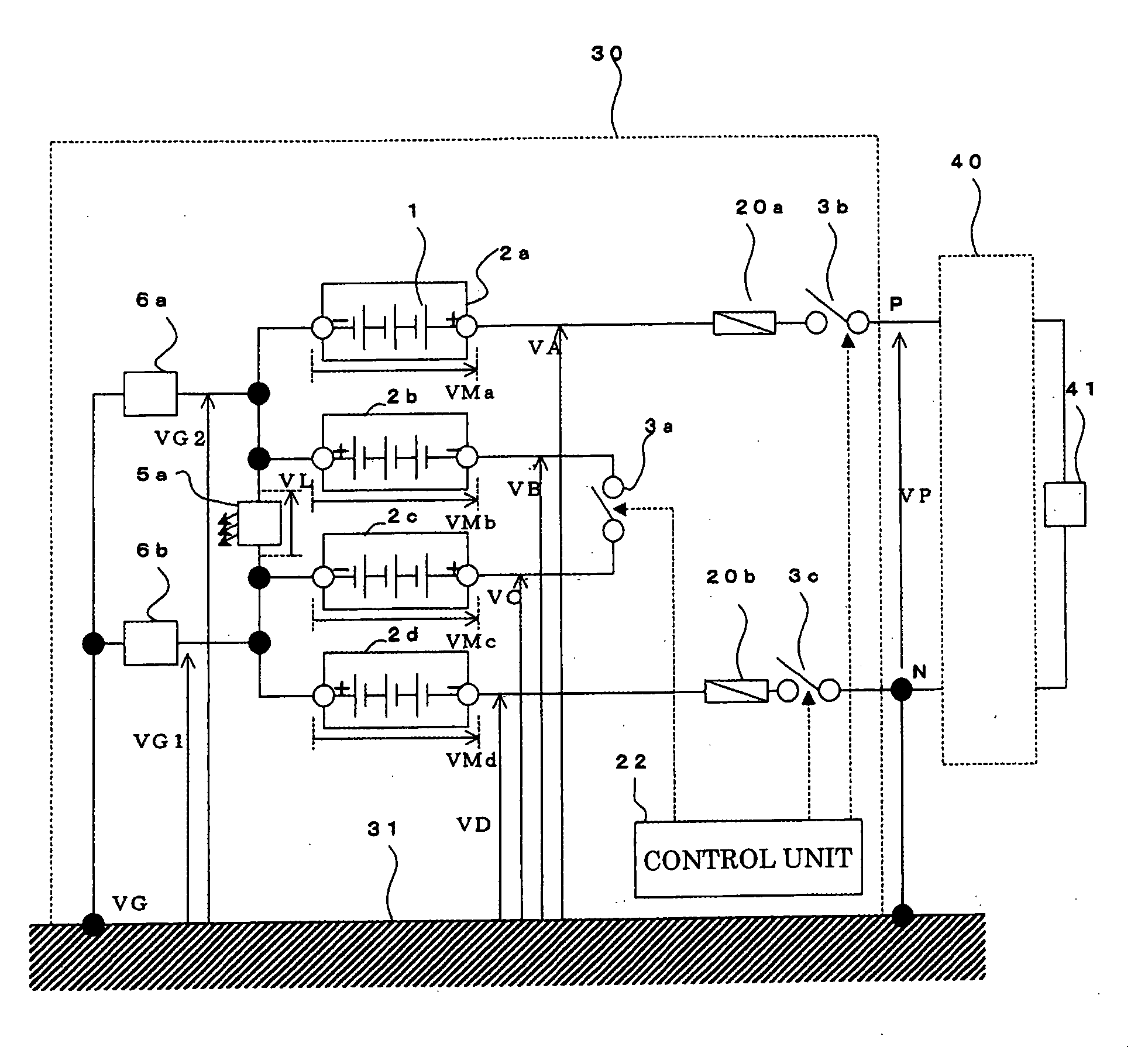
Power storage apparatus
a power storage and power technology, applied in the direction of battery/fuel cell control arrangement, cell components, capacitor propulsion, etc., can solve the problems of accelerating deterioration in the insulator extremely short life of etc., to reduce the voltage to ground at given positions in the power storage apparatus, suppress the progress of deterioration in the insulator, and reduce the voltage across the insulator (unillustrated).
- Summary
- Abstract
- Description
- Claims
- Application Information
AI Technical Summary
Benefits of technology
Problems solved by technology
Method used
Image
Examples
embodiment 1
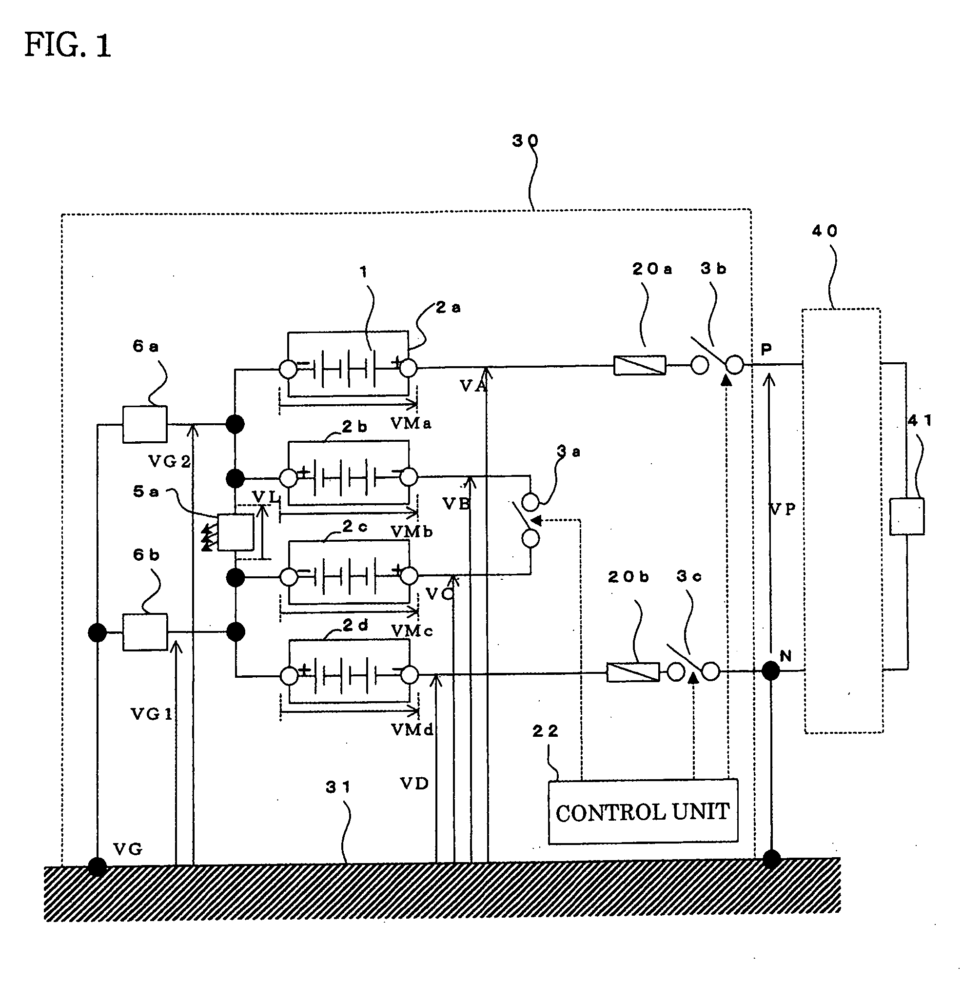
[0013]FIG. 1 is a diagram illustrating a configuration example of a power storage apparatus according to Embodiment 1 of the present invention. The configuration of a power storage apparatus 30 will be explained with reference to FIG. 1. As illustrated in FIG. 1, modules 2a to 2d, in each of which cells 1 are connected in a series-parallel fashion, are connected in series. A switch 3a (a second switch) is provided between the negative electrode terminal of the module 2b and the positive electrode terminal of the module 2c, thereby dividing the modules 2a to 2d into two groups, i.e., a group of the modules 2a and 2b and a group of the modules 2c and 2d. Additionally, a display device 5a is provided between the positive electrode terminal of the module 2b and the negative electrode terminal of the module 2c. In this case, the display device 5a, which is a device for visually indicating whether or not a voltage exists, by, e.g., blinking an LED, operates when a specific voltage is gene...
embodiment 2
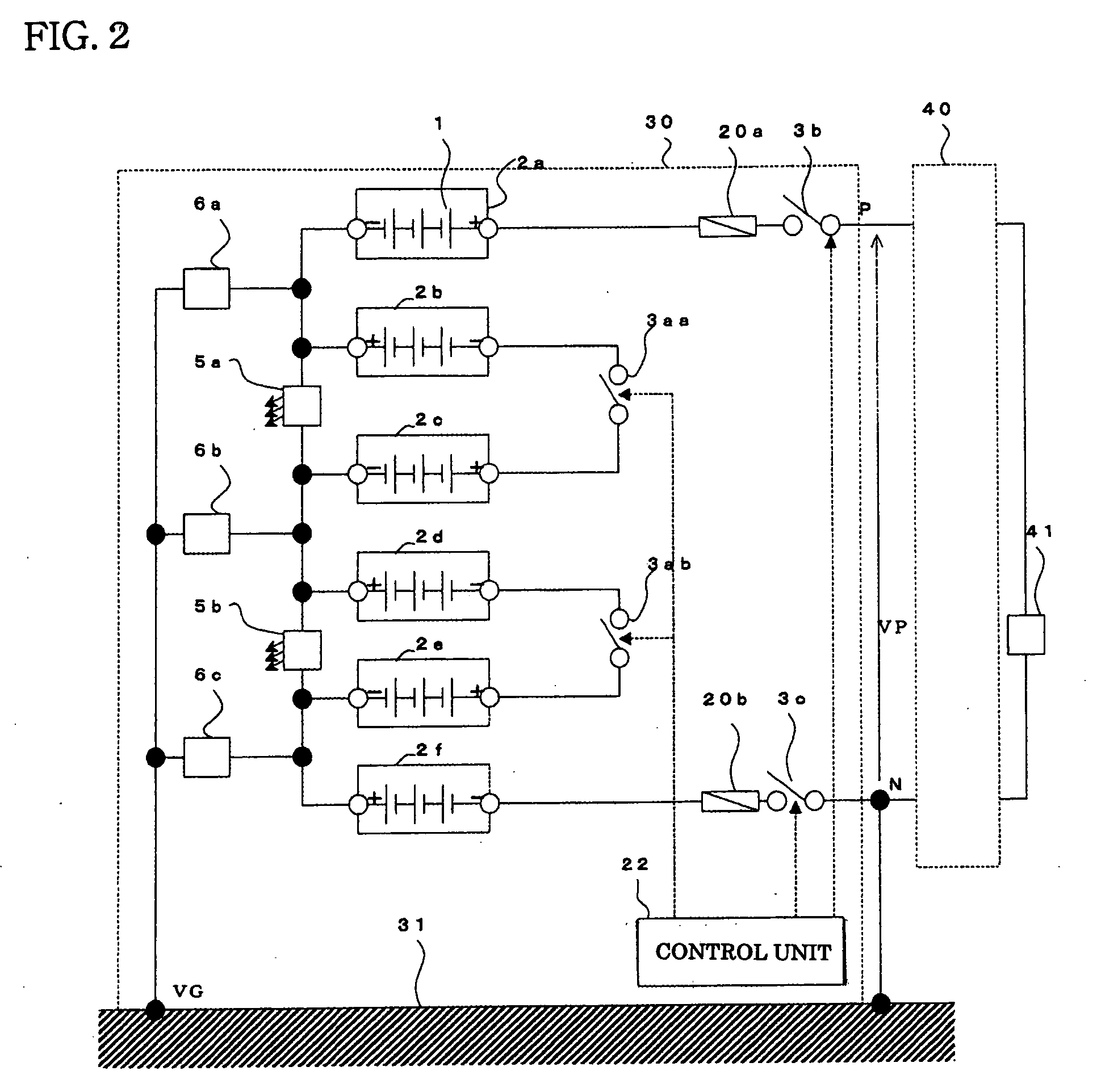
[0032]FIG. 2 is a diagram illustrating a configuration example of a power storage apparatus according to Embodiment 2 of the present invention. FIG. 2 illustrates a configuration example in the case where the number of modules is six; the configuration is in such a way that modules 2e and 2f are added. In contrast to FIG. 1 which illustrates a case in which the number of modules is four, the configuration is in such a way that a switch 3ab is connected between the negative electrode of the module 2d and the positive electrode of the module 2e, a display device 5b is connected between the positive electrode of the module 2d and the negative electrode of the module 2e, and the connection point where the module 2e and the module 2f are connected is grounded to the reference electric potential plane 31, by way of a grounding resistor 6c.
[0033]As far as the operation is concerned, in the case where the number of modules is six, the explanation is the same as that for the case where the ...
embodiment 3
[0034]FIG. 3 is a diagram illustrating a configuration example of a power storage apparatus according to Embodiment 3 of the present invention. FIG. 3 is a diagram illustrating a configuration example in the case where the number of modules is two. The same reference characters in FIG. 3 denote the same or equivalent constituent elements as those in FIGS. 1 and 2. In the case where the number of modules is two, the configuration is in such a way that the connection point where the modules 2a and 2b are connected is connected to the reference electric potential plane 31, by way of the grounding resistor 6a. With the configuration according to Embodiment 3, the maximal voltage to ground in the power storage apparatus is VP while the apparatus is operated; the maximal voltage to ground in the power storage apparatus is half of VP while the apparatus is not operated.
[0035]As described above, with configurations in Embodiments 1 to 3 of the present invention, in the case where the power ...
PUM
| Property | Measurement | Unit |
|---|---|---|
| voltage | aaaaa | aaaaa |
| current | aaaaa | aaaaa |
| voltage | aaaaa | aaaaa |
Abstract
Description
Claims
Application Information
 - R&D
- Intellectual Property
- Life Sciences
- Materials
- Tech Scout
- Unparalleled Data Quality
- Higher Quality Content
- 60% Fewer Hallucinations
Browse by: Latest US Patents, China's latest patents, Technical Efficacy Thesaurus, Application Domain, Technology Topic, Popular Technical Reports.
© 2025 PatSnap. All rights reserved.Legal|Privacy policy|Modern Slavery Act Transparency Statement|Sitemap|About US| Contact US: help@patsnap.com


