Cooling system for a turbocharged marine propulsion device

a cooling system and turbocharger technology, applied in marine propulsion, propulsive elements, vessel construction, etc., can solve the problems of poor fuel economy and unsatisfactory situation of turbocharger exhaust scroll cooling

Inactive Publication Date: 2009-05-21
BRUNSWICK CORPORATION
View PDF14 Cites 45 Cited by
  • Summary
  • Abstract
  • Description
  • Claims
  • Application Information

AI Technical Summary

Problems solved by technology

These cold temperatures could create an undesirable situation for turbocharger exhaust scroll cooling.
These undesirable situations relate to the presence of large thermal gradients in the system and excessive heat removal from the exhaust gas, particularly prior to the passage of the exhaust gas through the turbine portion of the turbocharger.
In addition, in four stroke outboard engines, the use of very cold water can result in oil dilution, by fuel, and poor fuel preparation that can result in poor fuel economy.

Method used


Image

  • Cooling system for a turbocharged marine propulsion device
  • Cooling system for a turbocharged marine propulsion device
  • Cooling system for a turbocharged marine propulsion device

Examples


Embodiment Construction

[0025]Throughout the description of the preferred embodiment of the present invention, like components will be identified by like reference numerals.

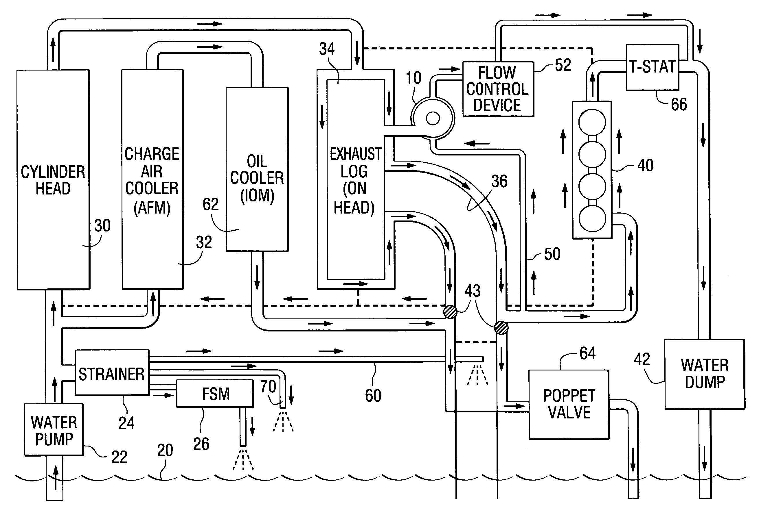
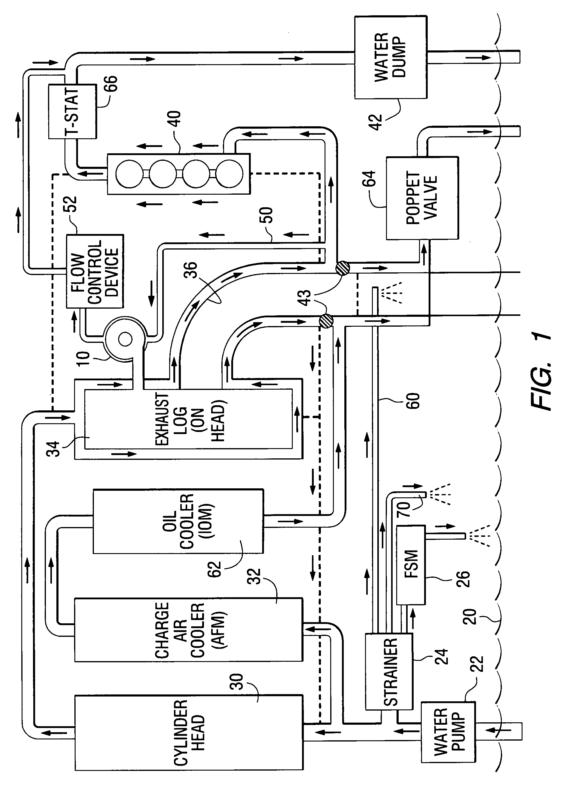
[0026]FIG. 1 is a schematic representation of a marine propulsion device, such as an outboard motor, which includes a turbocharger 10. The illustration in FIG. 1 is intentionally shown in a highly schematic fashion in order to describe the sequence and path of cooling water as it flows through the various heat emitting components of the system. Water is pumped from a body of water 20 by a water pump 22. Some of the water from the water pump 22 is directed through a strainer 24 and flows through a fuel system module 26. A significant portion of the water flowing from the water pump 22 is directed to the cylinder head 30 of the engine and a charge air cooler 32. The water flowing through the cylinder head 30 then passes to the exhaust manifold 34 which is sometimes referred to by those skilled in the art as the exhaust log. In the example...


PUM


Abstract

A cooling system for a marine engine having a turbocharger provides for the flow of coolant through heat emitting objects prior to flowing through a coolant jacket of the turbocharger itself. This avoids the potentially disadvantageous circumstance of directing cold water directly from a body of water through the cooling jacket of the turbocharger. Both open loop and closed loop versions of the invention are illustrated and described.

Description

BACKGROUND OF THE INVENTION[0001]1. Field of the Invention[0002]The present invention relates generally to a marine propulsion device that is provided with a turbocharger and, more particularly, to an outboard motor that provides a cooling system for a turbocharger which maintains a desirable operating temperature of the turbocharger.[0003]2. Description of the Related Art[0004]Turbochargers are well known to those skilled in the art of engine design. They have been used in conjunction with marine engines, both in sterndrive applications and outboard motors.[0005]U.S. Pat. No. 3,998,055, which issued to Bradford et al. on Dec. 21, 1976, describes a turbocharger for marine engines. It includes a dual chamber block interposed between the carburetor and the turbocharger. The block includes a first chamber for receipt of a fuel air mixture and a second chamber separated by a heat transfer wall from the first chamber. The second chamber receives hot water from the cooling system of the e...

Claims


Application Information

Patent Timeline
Patent Type & Authority Applications(United States)
IPC IPC(8): B63H20/28F01P3/20F02B33/00
CPCF01N3/046F01P3/207F01P2003/027F01P2003/028F01P2050/04Y02T10/20F01P2060/02F01P2060/04F01P2060/16F02B39/005F01P2050/06Y02T10/12
Inventor TAYLOR, CHRISTOPHER J.REID, TIMOTHY S.DAVIS, RICHARD A.BELTER, DAVID J.FUOSS, KLAUS
Owner BRUNSWICK CORPORATION
Why Eureka
Try Eureka