
Wireless communication system and test method thereof, and access terminal for testing wireless communication system

a wireless communication system and access terminal technology, applied in the direction of optical radiation measurement, transmission monitoring, receiver monitoring, etc., can solve the problems of increasing the cost required to sustain the communication system, affecting the fee and charge of users, etc., and achieve the effect of simple procedure and simple procedur

Active Publication Date: 2009-05-21
FIPA FROHWITTER INTPROP AG
View PDF7 Cites 9 Cited by
  • Summary
  • Abstract
  • Description
  • Claims
  • Application Information

AI Technical Summary

Benefits of technology

"The present invention provides a wireless communication system and its test method that can execute a test of a wireless communication apparatus from a remote place while suppressing the introduction of special apparatuses and dispatching maintenance engineers to the cell to the utmost. The invention uses a general terminal obtained by installing a test AP on a terminal that is used in general wireless communication systems and that can execute APs via a communication network. The terminal conducts communication the maintenance center by using control signals and test signals for test, and notifies the maintenance center of an actual measurement result obtained at the terminal. The invention provides a simple and low-cost configuration and a simple procedure for testing a wireless communication system."

Problems solved by technology

In the method of making a test of the communication network by dispatching a maintenance engineer to each cell associated with a base station and carrying a terminal and a tester in the cell, remarkable human resources are used and consequently the cost required to sustain the communication system increases and finally the fee and charge of users are also affected.

Method used


Image

  • Wireless communication system and test method thereof, and access terminal for testing wireless communication system
  • Wireless communication system and test method thereof, and access terminal for testing wireless communication system
  • Wireless communication system and test method thereof, and access terminal for testing wireless communication system

Examples


Embodiment Construction

[0040]Hereafter, embodiments of a configuration of a wireless communication system according to the present invention, its test method, and a configuration of a terminal apparatus used to make a test of the wireless communication system will be described with reference to the drawings.

[0041]Hereafter, they will be described in detail by mainly taking a wireless communication system that provides packet communication as an example.

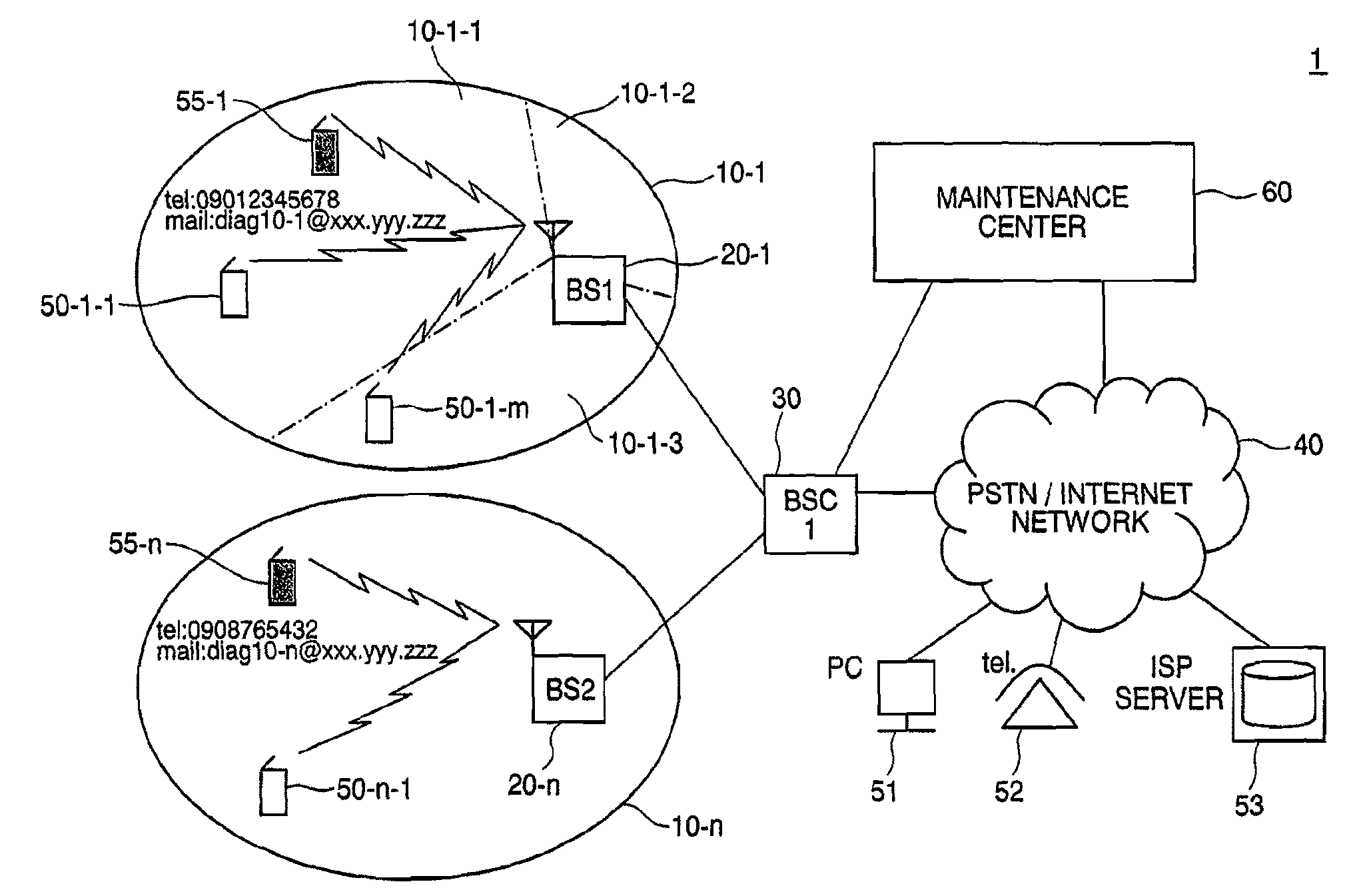
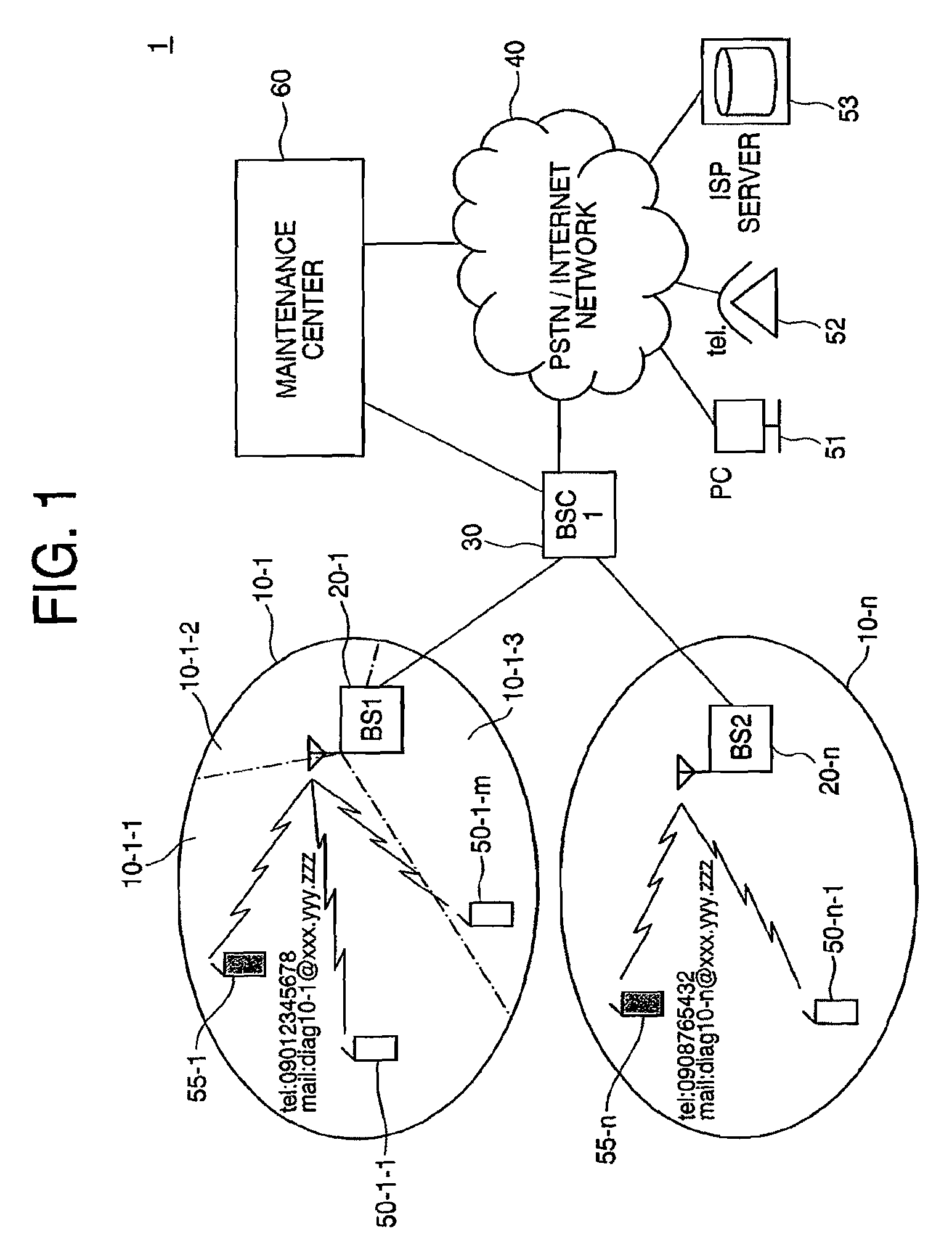
[0042]FIG. 1 is a system configuration diagram showing a configuration example of a wireless communication system. A wireless communication system 1 includes a base station (hereafter referred to as BS) 20 serving as a wireless communication apparatus which conducts communication with terminals 50; a base station controller (hereafter referred to as BSC) 30 which conducts connection with the BS 20, connection with a PSTN / Internet (hereafter referred to collectively as PSTN) 40 serving as another communication network, and management and control of the BS 20...


PUM


Abstract

A wireless communication system and its test method capable of executing a test of the wireless communication apparatus from a remote place by using a terminal generally used in wireless communication systems are implemented with a low-cost configuration and a simple procedure. A terminal obtained by installing a test AP on a general terminal that is used in general wireless communication systems and that can execute APs via a communication network is placed in a coverage area of a wireless communication apparatus. A maintenance center for the wireless communication system activates the terminal. The terminal executes the test AP and conducts communication with the maintenance center by using control signals and test signals for testing wireless communication system. A test is executed by measuring an actual communication state of the wireless communication system.

Description

INCORPORATION BY REFERENCE[0001]The present application claims priority from Japanese applications JP 2004-212451 filed on Jul. 21, 2004 and JP 2004-341379 filed on Nov. 26, 2004, the contents of which are hereby incorporated by reference into this application.BACKGROUND OF THE INVENTION[0002]The present invention relates to a configuration and a test method of a wireless communication system.[0003]Besides the conventional wire communication network, introduction of a wireless communication network (hereafter referred to as wireless communication system) using access terminals and wireless communication apparatuses is advancing. In the wireless communication system, CDMA (Code Division Multiple Access) communication in which a signal of voice or the like is subject to code multiplexing with the spreading code to conduct communication is spread, besides the TDMA (Time Division Multiple Access) communication in which a signal of voice or the like is subject to time division multiplexi...

Claims


Application Information

Patent Timeline
Patent Type & Authority Applications(United States)
IPC IPC(8): H04W24/00H04B17/00H04B17/18H04B17/29H04M1/00H04M11/00H04W8/24H04W24/06H04W24/08H04W24/10H04W88/02
CPCH04W24/06H04W8/245G02F1/1309G02F1/1336G01J1/02B65G49/061
Inventor UCHIDA, TSUTOMUHAYATA, KOJIAOE, HIDEO
Owner FIPA FROHWITTER INTPROP AG
Learn More