Implantable medical marker and methods of preparation thereof

Inactive Publication Date: 2009-05-21
NAVOTEK MEDICAL
View PDF98 Cites 69 Cited by
  • Summary
  • Abstract
  • Description
  • Claims
  • Application Information

AI Technical Summary

Benefits of technology

[0134]wherein the amorphous mass is adapted to prevent di

Problems solved by technology

In some cases, medical imaging provides a relative location of the marker with respect to an anatomic location, but does not provide an absolute location of the marker in terms of position co-ordinates.
In other cases, a dedicated detection device provides an absolute location of the marker in terms of position co-ordinat

Method used


Image

  • Implantable medical marker and methods of preparation thereof
  • Implantable medical marker and methods of preparation thereof
  • Implantable medical marker and methods of preparation thereof

Examples


Example

Overview

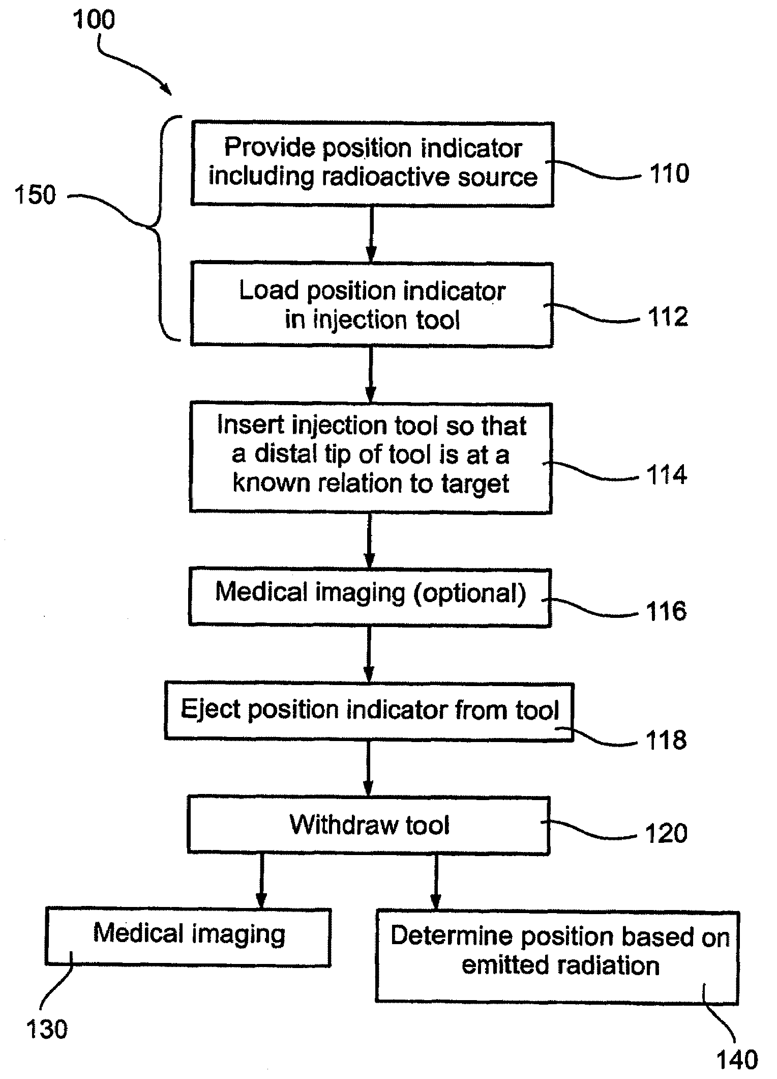
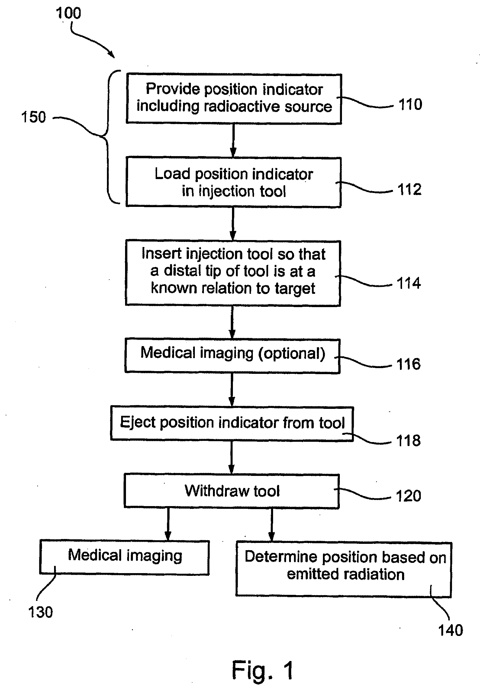
[0148]FIG. 1 is a simplified flow diagram of an implantation procedure 300 according to an exemplary embodiment of the invention.

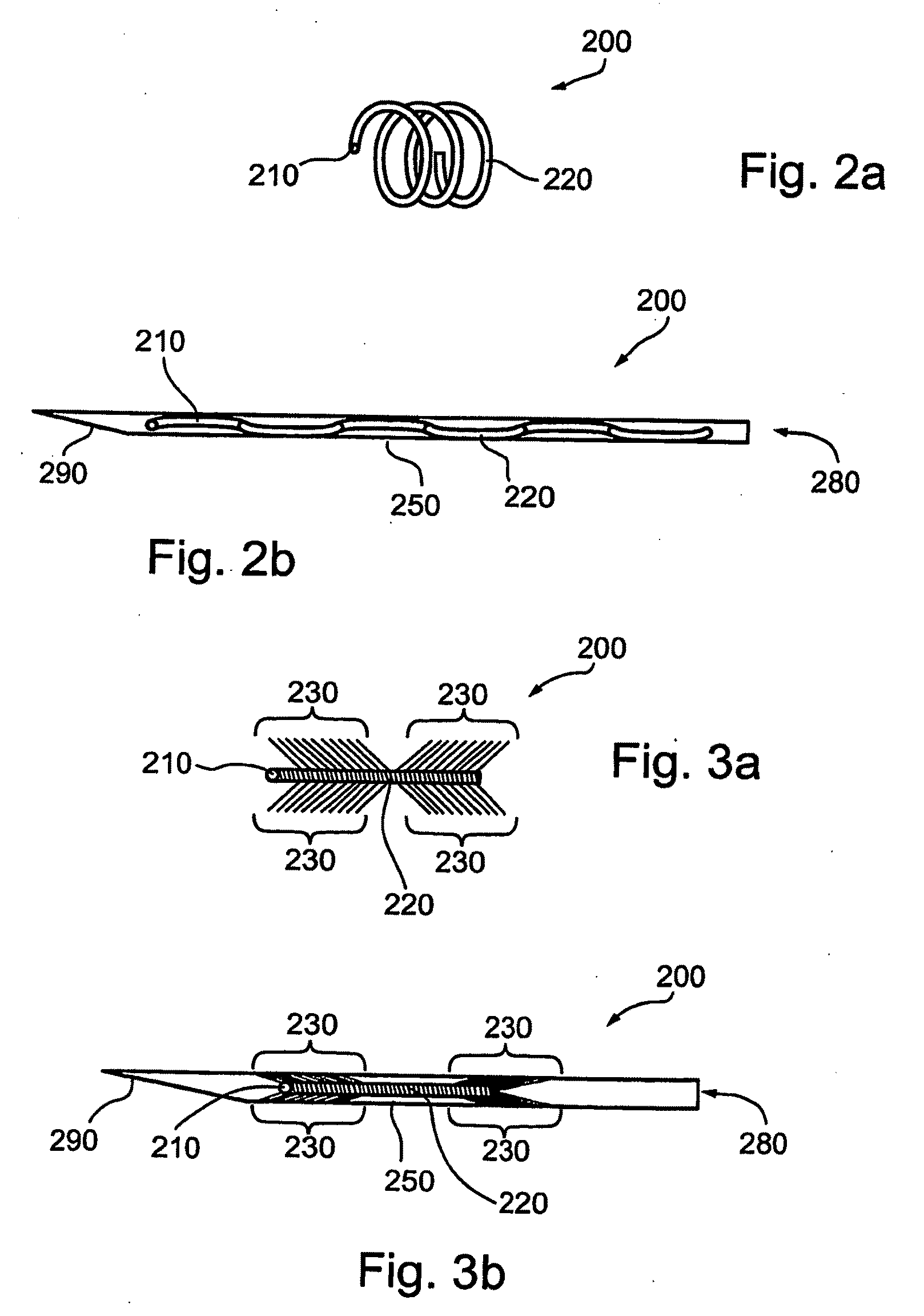
[0149]At 110 an implantable marker including a radioactive source adapted to function as a marker is provided. According to some exemplary embodiments of the invention, the marker comprises a wire. Optionally, the marker is longer than an injection tool into which it will be loaded for injection. In an exemplary embodiment of the invention, the wire is coiled, folded or disorganized (e.g. jumbled) and then compressed to facilitate loading into the injection tool. Optionally, a degree of coiling folding or jumbling varies along an axial length of the marker. In an exemplary embodiment of the invention, disorganized sections are axially distributed along the marker at intervals, optionally regular intervals.

[0150]At 112, the marker is loaded into an injection tool. 150 indicates that 110 and 112 may optionally be performed at a manufacturing facility...


PUM


Abstract

An implantable medical marker, the marker comprising a marker body adapted for insertion via a needle and adapted to define a volume with a smallest dimension larger than an inner diameter of the needle; and a radiation source—characterized by gamma emissions sufficient to exit the human body.

Description

RELATED APPLICATIONS[0001]This application is a Continuation in part of International application PCT / IB2006 / 052771 filed on Aug. 10, 2006 entitled “Medical Treatment System and Method” and is also a Continuation in part of International Patent Application PCT IB2006 / 052770 filed on Aug. 10, 2006 and entitled “Localization of a Radioactive Source”.[0002]This application also claims priority from U.S. Provisional Applications:[0003]60 / 773,931 filed on Feb. 16, 2006, entitled “Radiation Oncology Application”;[0004]60 / 773,930 filed Feb. 16, 2006, entitled “Localization of a Radioactive Source”;[0005]60 / 804,178 filed on Jun. 8, 2006, entitled “Radioactive Medical Implants”;[0006]The disclosures of these international and provisional applications are each fully incorporated herein by reference.[0007]This application is related to:[0008]PCT / IL2005 / 000871 filed on Aug. 11, 2005, entitled “Localization of a Radioactive Source within a Body of a Subject”; and[0009]PCT / IL2005 / 001101 filed on ...

Claims


Application Information

Patent Timeline
IPC IPC(8): A61M36/12
CPCA61B5/1127A61N5/1049A61N5/1067A61N5/1069A61N2005/1051A61B34/20A61B90/39A61B2034/2068A61B2090/101A61B2090/3908A61B2090/392A61B2090/3987
Inventor NEUSTADTER, DAVID MAIERKORNBLAU, GIORA
Owner NAVOTEK MEDICAL
Why Eureka
Try Eureka