Dynamically Matched Microwave Antenna for Tissue Ablation

a dynamic matching and tissue ablation technology, applied in the field of microwave applicator probes, can solve the problems of inability to maintain a predetermined impedance match between the microwave delivery system (e.g., generator, cable, etc., and the tissue surrounding the microwave probe, and achieve the effect of avoiding the detunement of the narrow band microwave prob

Active Publication Date: 2009-05-21
TYCO HEALTHCARE GRP LP
View PDF70 Cites 81 Cited by
  • Summary
  • Abstract
  • Description
  • Claims
  • Application Information

AI Technical Summary

Benefits of technology

[0009]The present disclosure provides for a microwave ablation probe which can be dynamically matched and / or tuned during ablation. As tissue is ablated, the radiating portion of the probe is actively tuned so that an optimal impedance match is achieved for a desired procedure. This is accomplished by adjusting the shape, size and / or dielectric properties of the components of the probe (e.g., adjusting the length of the conductors, insulating layers, and the like). In monopole and / or dipole antennas, the length of an inner conductor is adjusted to create a more efficient radiator. In dipole antennas, the length of the outer and inner conductors is adjusted such that a predetermined wavelength distance at the radiating portion is maintained despite frequency changes (e.g., inner and outer conductors being ¼ wavelength long to maintain balanced behavior of a ½ wavelength dipole). In another embodiment, dielectric properties of the radiating portion are adjusted by using materials with thermally changing dielectric properties; thus, as the temperature of the tissue and the probe changes during ablation the dielectric properties of the probe are automatically adjusted.

Problems solved by technology

Conventional microwave probes have a narrow operational bandwidth, a wavelength range at which optimal operational efficiency is achieved, and hence, are incapable of maintaining a predetermined impedance match between the microwave delivery system (e.g., generator, cable, etc.) and the tissue surrounding the microwave probe.
As a result, there is a mismatch between the bandwidth of conventional microwave probe and the microwave energy being applied.
Thus, narrow band microwave probes may detune as a result of steam generation and phase transformation of the tissue hindering effective energy delivery and dispersion.

Method used


Image

  • Dynamically Matched Microwave Antenna for Tissue Ablation
  • Dynamically Matched Microwave Antenna for Tissue Ablation
  • Dynamically Matched Microwave Antenna for Tissue Ablation

Examples


Embodiment Construction

[0019]Particular embodiments of the present disclosure will be described herein below with reference to the accompanying drawings. In the following description, well-known functions or constructions are not described in detail to avoid obscuring the present disclosure in unnecessary detail.

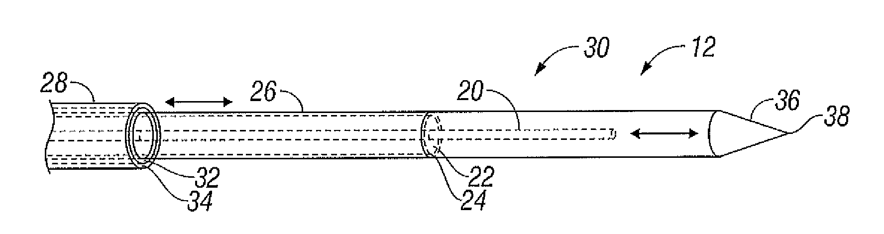
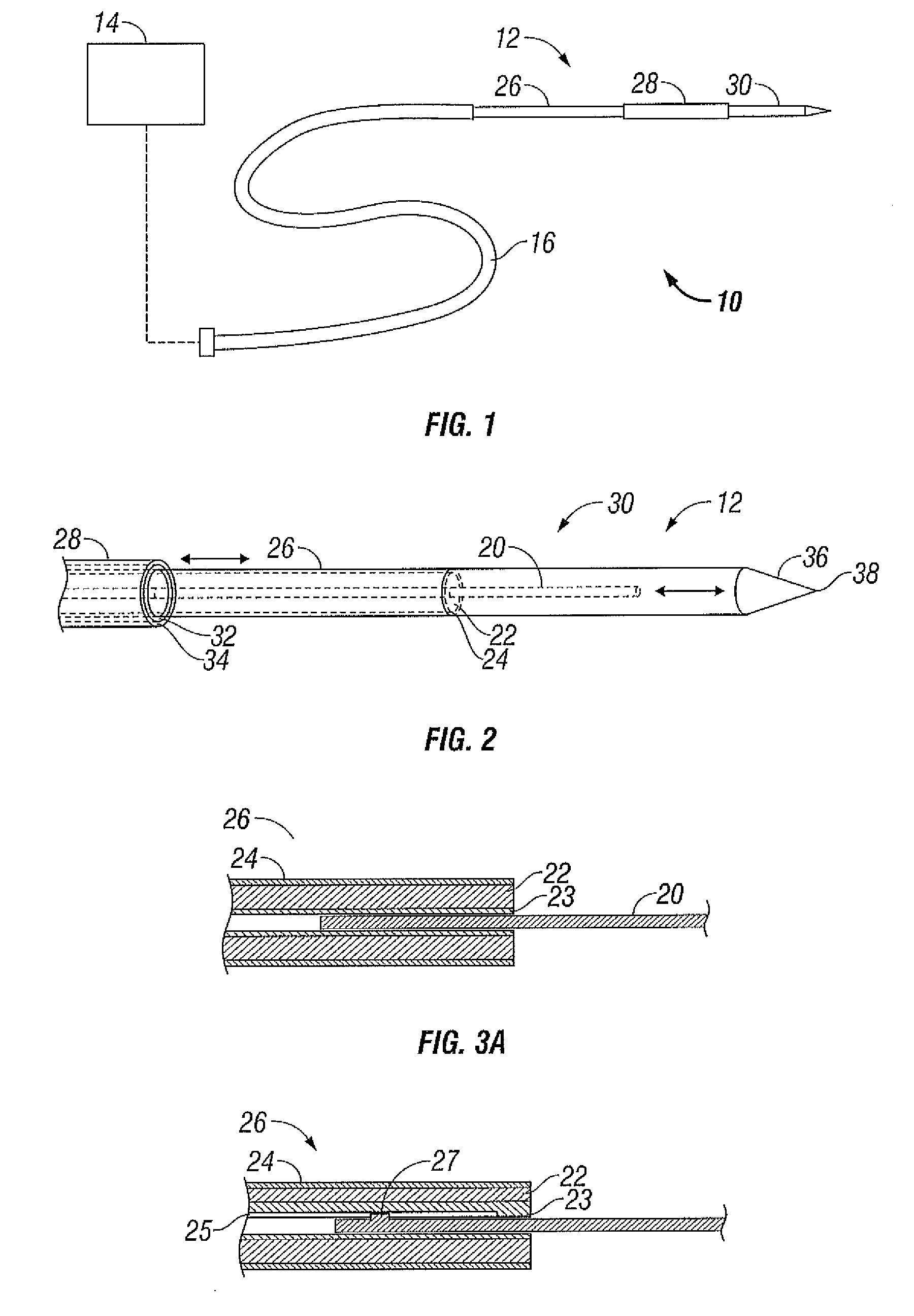
[0020]FIG. 1 shows a microwave ablation system 10 which includes a microwave ablation probe 12 coupled to a microwave generator 14 via a flexible coaxial cable 16 that is coupled to a connector 18 of the generator 14. The generator 14 is configured to provide microwave energy at an operational frequency from about 500 MHz to about 2500 MHz.

[0021]During microwave ablation, the probe 12 is inserted into tissue and microwave energy is supplied thereto. As tissue surrounding the probe 12 is ablated, the tissue undergoes desiccation and denaturization which results in a drop of the effective dielectric constant of the tissue. The drop in the effective dielectric constant, in turn, lengthens the wavelen...


PUM


Abstract

A microwave ablation probe for providing microwave energy to tissue is disclosed. The probe includes a feedline having an inner conductor, a secondary inner conductor, an insulating spacer, and an outer conductor. The inner conductor is slidably disposed within the secondary inner conductor. The feedline also includes a radiating portion having an extruded portion of the inner conductor centrally disposed therein, wherein longitudinal movement of the inner conductor relative to the feedline tunes the radiating portion.

Description

CROSS-REFERENCE TO RELATED APPLICATION[0001]The present application claims the benefit of priority to U.S. Provisional Application Ser. No. 60 / 988,699 filed on Nov. 16, 2007, which is incorporated by reference herein.BACKGROUND[0002]1. Technical Field[0003]The present disclosure relates generally to microwave applicator probes used in tissue ablation procedures. More particularly, the present disclosure is directed to a microwave probe that can be tuned during ablation procedures to obtain a desired impedance match.[0004]2. Background of Related Art[0005]Treatment of certain diseases requires destruction of malignant tissue growths (e.g., tumors). It is known that tumor cells denature at elevated temperatures that are slightly lower than temperatures injurious to surrounding healthy cells. Therefore, known treatment methods, such as hyperthermia therapy, heat tumor cells to temperatures above 41° C., while maintaining adjacent healthy cells at lower temperatures to avoid irreversibl...

Claims


Application Information

Patent Timeline
Patent Type & Authority Applications(United States)
IPC IPC(8): A61B18/18
CPCA61B18/18H01Q9/30H01Q1/02A61B18/1815A61B2018/00577A61B2018/1838A61B2018/1853
Inventor RUSIN, CHRISTOPHER T.BRANNAN, JOSEPH
Owner TYCO HEALTHCARE GRP LP
Why Eureka
Try Eureka