Mobile spine stabilization device

a stabilizing device and spine technology, applied in the field of orthopaedic stabilization devices, can solve the problems of not being able to resist compression or shear loads, not being able to minimize the shear force between the vertebral bodies being stabilized, and long recovery process, etc., to achieve controlled flexion and extension motions of the spine, limiting the range of relative motion, and reducing the effect of compression and shear forces

Inactive Publication Date: 2009-05-21
WHITE PATRICK
View PDF41 Cites 65 Cited by
  • Summary
  • Abstract
  • Description
  • Claims
  • Application Information

AI Technical Summary

Benefits of technology

[0024]An advantage of the present invention is a device that limits the range of relative motion between two vertebral bodies and works with existing pedicle screw assemblies.
[0025]Another advantage of the invention is to constrain the motion between vertebral bodies in a ductile manor.
[0026]Another advantage is to allow controlled flexion and extension motions of the spine while constraining bending and shear forces.
[0027]Another advantage of the invention is to provide a kit to the surgeon that has a variety of pedicle screws, rigid fusion rods, and elongated implantable ductile ligaments. Further, it is desirable that the ligaments provide a variety of stiffness and flexibility options so the surgeon can select the appropriate stiffness and range of motion to achieve the desired surgical result whether it is for aiding fusion or restoring normal range of motion to a patient.

Problems solved by technology

In attempting to fuse the patient there is a long and painful recovery process.
Most rod and screw constructs and fusion cage constructs are very rigid, not allowing transfer of stress into the fusion site that would otherwise aid in a quicker recovery.
Many are working to develop devices that allow relative motion, yet these have fallen short in minimizing shear forces between the vertebral bodies being stabilized.
While the ligaments allow for relative motion, they do not appear to resist compression or shear loads, instead relying upon tension alone.
This design provides flexural degrees of freedom, allows relative motion between the vertebral bodies, but does little to inhibit or prevent shearing between the vertebral bodies.
While flexibility in translation can be helpful, the spine loads in several planes at the same time and the translation spoken of in this patent would appear to inadequately redistribute stresses through the fusion site.
As a result motion is forcibly limited to one location, i.e., motion is constrained through a hinge point, which undesirably stresses the assembly construct.
The disclosed design attempts to accomplish a multidirectional redistribution of force for aiding in quicker fusion rates, however its constructs were not designed for use in conjunction with a disk implant.
This constrains force through the rod in a manner causing early fatigue failure.
Further, the rod cannot be bent at the time of surgery to a preformed shape holding the vertebral bodies in a desired relative position while also limiting their relative motion.

Method used


Image

  • Mobile spine stabilization device
  • Mobile spine stabilization device
  • Mobile spine stabilization device

Examples


example 1

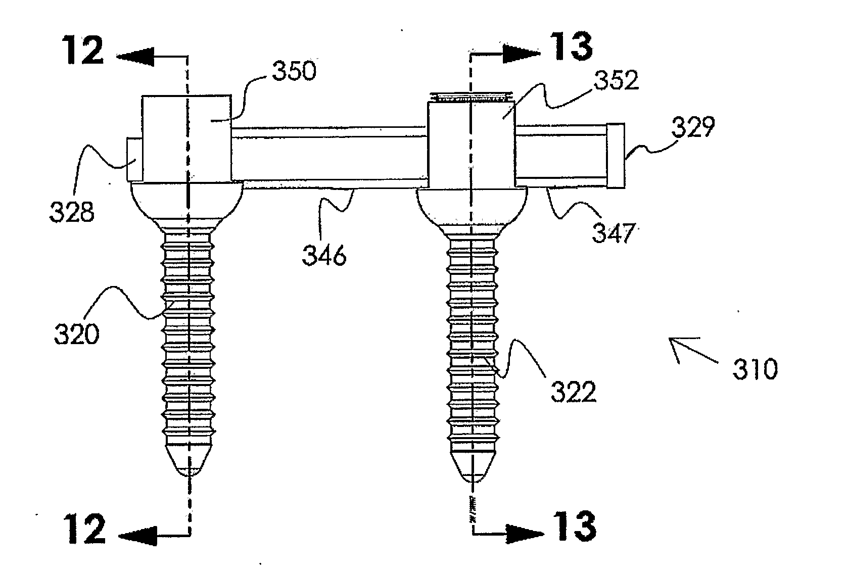
[0062]A single level spinal construct consisting of a pair of nitinol rods each 76 mm in length and 5.5 mm in diameter and having a martensite / austenite transition temperature of 200 degrees Fahrenheit (95 degrees centigrade) was prepared using DENALI™ spinal screws (available from K2M, LLC, Leesburg, Va., under the designation K2M 40) was tested pursuant to ASTM testing standard F 1717-04 (Spinal Implant Constructs in a Verbrectomy Model). The results are shown in Table 1.

TABLE 1Nominal LoadTestDuring TestNumber(Newtons)CyclesResult1+ / −110 N5,000,000Runout(+ / −5 N variance)2+ / −110 N5,000,000Runout(+ / −5 N variance)

[0063]The results reported in Table 1 show that a 5.5 mm diameter nitinol rod having a martensite / austenite transition temperature of about 200 degrees Fahrenheit (95 degrees centigrade) can withstand 5 million cycles at 110 N load.


PUM


Abstract

An orthopedic device is described for stabilizing the spinal column between first and second vertebral bodies. The device has first and second screws adapted for fixation to the first and second vertebral bodies, respectively. The device further includes an elongated ligament with a first end connected to the first screw and the second end operatively connected with the second screw. The ligament is made preferably of a nickel titanium alloy selected to have ductile inelastic properties at body temperature and is capable of plastic deformation to allow relative constrained motion between the vertebral bodies. The preferred nickel titanium has a martensite / austenite transition temperature above body temperature. In a preferred embodiment, the second pedicle screw includes a bearing for receiving the ligament in a slidably engageable relationship. The device further includes optional first and second dampening members surrounding the ligament for restraining the spinal column during flexion and extension.

Description

CROSS-REFERENCE TO RELATED APPLICATIONS[0001]This application is a continuation-in-part of U.S. patent application Ser. No. 11 / 321,337, filed on Dec. 29, 2005, which is a continuation-in-part of U.S. application Ser. No. 11 / 244,184, filed Oct. 5, 2005, which claims priority to, and the benefit of, U.S. Provisional Patent Application Ser. No. 60 / 677,699, filed on May 4, 2005, the entire disclosures of which are expressly incorporated by reference herein.BACKGROUND OF THE INVENTION[0002]1. Technical Field of the Invention[0003]The present invention relates to orthopedic stabilization devices used to limit the relative motion of at least two vertebral bodies for the relief of pain. These devices can be used to aid osteo-synthesis in combination with fusion devices, supplement other motion restoring devices such as disk implants or used solely to restrict the motion of vertebral bodies without other devices.[0004]2. Description of the Related Art[0005]In the field of spine surgery, ther...

Claims


Application Information

Patent Timeline
Patent Type & Authority Applications(United States)
IPC IPC(8): A61B17/70A61B17/04
CPCA61B17/7004A61B17/7011A61B17/702A61B17/7046A61B17/7031A61B17/7032A61B2017/00867A61B17/7029
Inventor WHITE, PATRICK M.
Owner WHITE PATRICK
Why Eureka
Try Eureka