Drive mechanism and gripper mechanism equipped with drive mechanism

a technology of drive mechanism and gripper, which is applied in the direction of mechanical control devices, process and machine control, instruments, etc., can solve the problems of potential drop of workpieces from the gripper, loss of generated force (drive torque) and loss of drive torqu

Active Publication Date: 2009-05-28
SMC CORP
View PDF10 Cites 25 Cited by
  • Summary
  • Abstract
  • Description
  • Claims
  • Application Information

AI Technical Summary

Benefits of technology

[0007]A general object of the present invention is to provide a drive mechanism and a gripper mechanism equipped with such a drive mechanism in which, in cases where a rotary power source is stopped in case of emergency or upon interruption of electrical power or the like, the gripper mechanism can maintain the pressed condition of a pressing member against a workpiece, even in cases when transmittal of a drive force to the pressing member from the rotary drive source is halted.

Problems solved by technology

However, generally, at times of emergency power stoppage, or when electrical power is interrupted, the generated force (drive torque) is lost, unless electrical energy is stored.
On the other hand, when electrical power to the motor is stopped in a state where the workpiece is gripped, there is a potential for the workpiece to be dropped from the gripper.

Method used


Image

  • Drive mechanism and gripper mechanism equipped with drive mechanism
  • Drive mechanism and gripper mechanism equipped with drive mechanism
  • Drive mechanism and gripper mechanism equipped with drive mechanism

Examples


Embodiment Construction

[0021]Below, detailed explanation shall be made with reference to the accompanying drawings concerning a drive mechanism according to the present invention and preferred embodiments relating to a gripper mechanism equipped with such a drive mechanism.

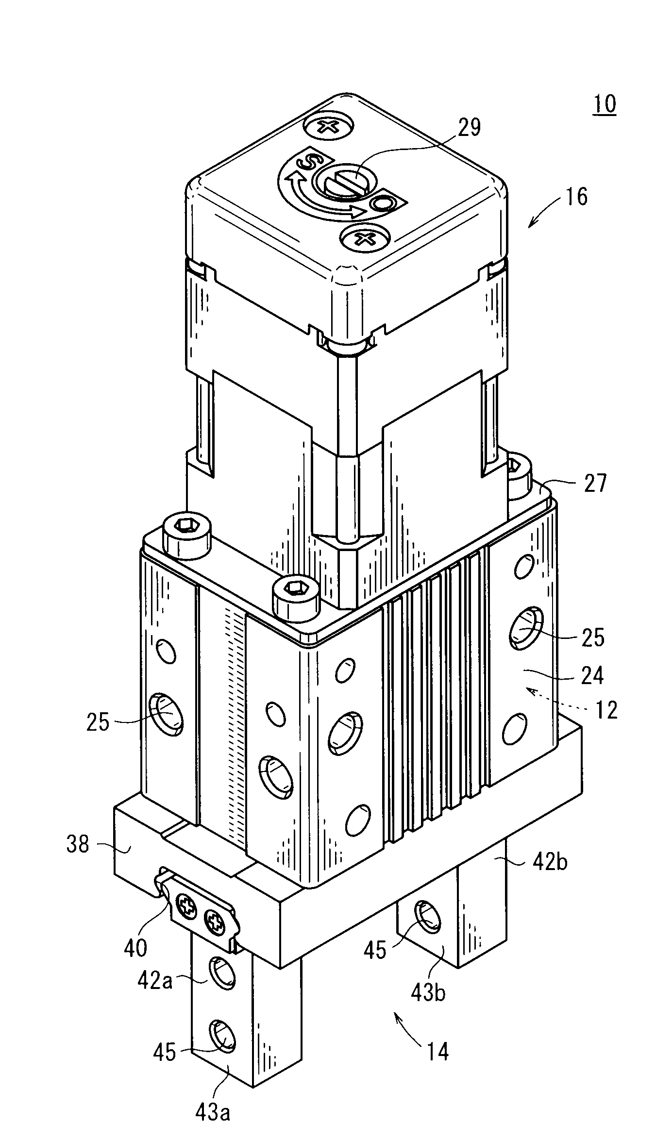
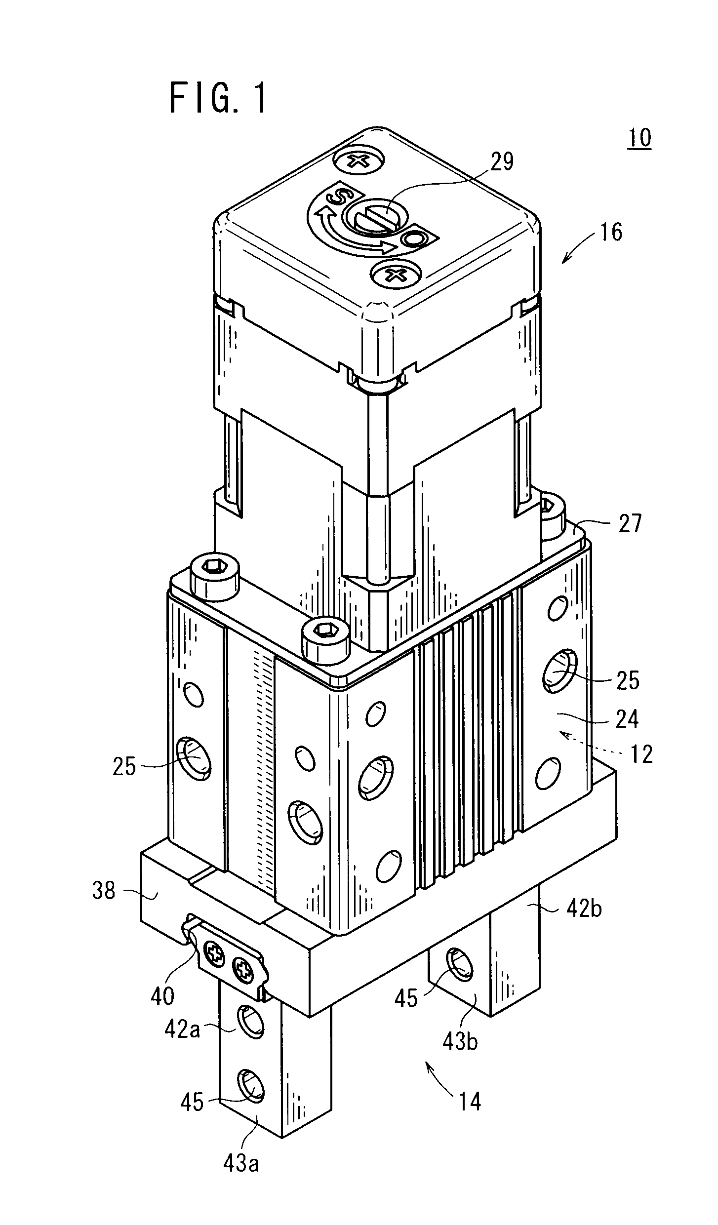
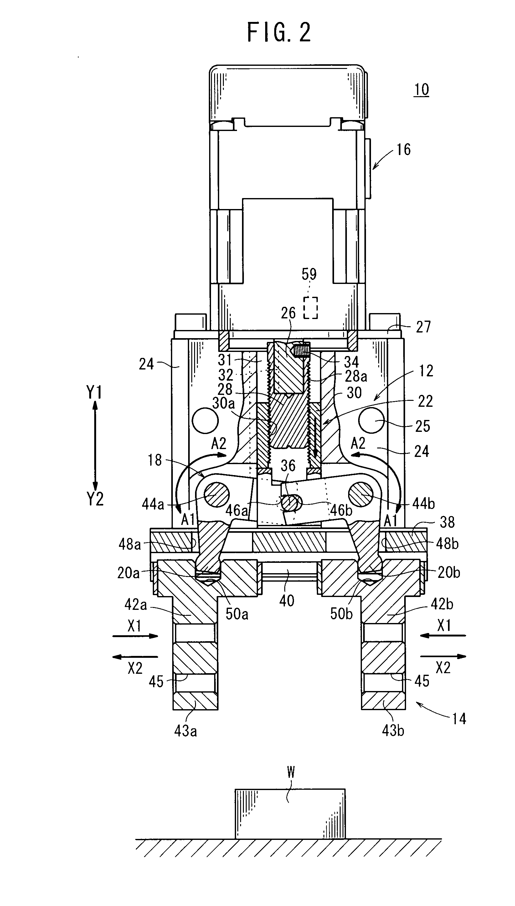
[0022]As shown in FIGS. 1 and 2, an electrical gripper (electrical chuck) 10, as a gripper mechanism according to a first embodiment, is equipped with a drive mechanism 12 according to an embodiment, and includes a gripper section (chuck section) 14 for gripping a workpiece W that forms an object to be gripped, which is used, for example, by attachment onto an end of a shaft of a machine tool, an industrial robot, or the like.

[0023]The electrical gripper 10 is constituted by the gripper section 14, a drive mechanism 12 for driving the gripper section 14, and a housing 24.

[0024]The drive mechanism 12 comprises a motor (rotary drive source) 16 making up a drive source for opening / closing the gripper section 14, a link mechanism 18 that ca...


PUM


Abstract

A drive mechanism and a gripper mechanism equipped with the drive mechanism are provided. An electrical gripper includes a drive mechanism equipped with a motor, a feed screw that transmits a rotary drive force from the motor to a feed nut capable of displacement in an axial direction, and a gripper section that grips a workpiece by coupling to the feed nut and being displaced thereby. The drive mechanism further is constituted by a self-locking mechanism, which prevents the feed nut from being retracted as a result of a reactive force received in the event that the feed nut is advanced and the workpiece is gripped by the gripper section.

Description

BACKGROUND OF THE INVENTION[0001]1. Field of the Invention[0002]The present invention relates to a drive mechanism, which is capable of pressing a workpiece by displacement of a displacement member under a driving action of a rotary drive source, and to a gripper mechanism equipped with such a drive mechanism.[0003]2. Description of the Related Art[0004]Heretofore, a drive mechanism has been used for pressing a workpiece by means of a displacement member, which is displaced under a driving action of a rotary drive source such as a motor or the like. For example, an electrical gripper (electrical chuck) for gripping various components or the like (workpieces) is known, the electrical gripper being attached to an end of a shaft or the like of a working machine, wherein an opening / closing operation of openable / closable gripper members is carried out using a drive force of the motor to grip the workpieces.[0005]As such an electrical gripper, in Japanese Laid-Open Patent Publication No. ...

Claims


Application Information

Patent Timeline
Patent Type & Authority Applications(United States)
IPC IPC(8): G05G11/00B66C1/00
CPCY10T74/20207B25J15/0273B25J13/02B25J15/00
Inventor FUKANO, YOSHIHIROMAKADO, SHOICHI
Owner SMC CORP
Why Eureka
Try Eureka