
Method for receiving fluid from a natural gas pipeline

a natural gas pipeline and fluid technology, applied in the direction of liquid degasification, separation process, borehole/well accessories, etc., can solve the problems of compromising the efficacy of slug catcher in such separation, and the shutting down of further downstream processing units, so as to achieve the effect of less cos

Active Publication Date: 2009-05-28
SHELL USA INC
View PDF8 Cites 17 Cited by
  • Summary
  • Abstract
  • Description
  • Claims
  • Application Information

AI Technical Summary

Benefits of technology

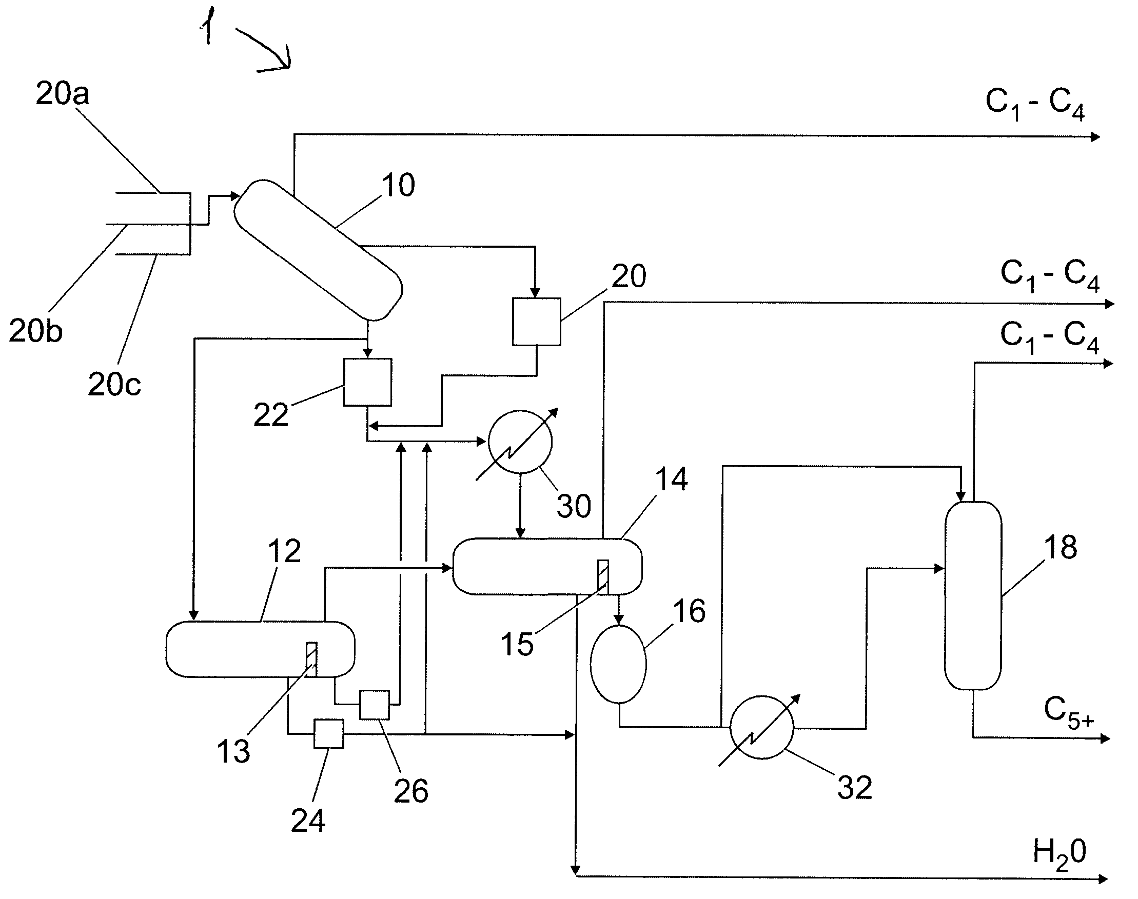
[0008]An important advantage of the method according to the invention is that it provides uninterrupted supply, even in the event of a surge, both of a stream of gaseous hydrocarbons to downstream gas processing and of liquid hydrocarbons to downstream liquid hydrocarbon processing.
[0009]Moreover, the slug catcher may be made much smaller than conventional slug catchers since it does not need the capacity to cope with the additional liquid volume received during surges. This is beneficial since the provision of the, typically lower pressure surge vessel, is less expensive than the, typically higher pressure, slug catcher.

Problems solved by technology

Natural gas pipelines from a natural gas reservoir of from a gas producing platform often contain significant amounts of liquids, such as hydrocarbon condensations and water, and optionally smaller amounts of solids that may interfere with the proper operation of downstream equipment and processes.
Although generally satisfactory, slug catcher's efficacy in such separation can be compromised in case of a surge, i.e. when an unexpectedly large slug of liquids and optionally solids is deposited in the slug catcher.
This can for example result in downstream equipment, such as a three-phase separator, being starved of gaseous hydrocarbons which may cause shut-down of further downstream processing units, e.g. an LNG plant, a Fischer-Tropsch plant or a methanol plant.

Method used


Image

  • Method for receiving fluid from a natural gas pipeline
  • Method for receiving fluid from a natural gas pipeline

Examples


Embodiment Construction

[0011]In step (a) of the method according to the invention, fluid from at least one natural gas pipeline is received in a slug catcher. The fluid comprises gaseous hydrocarbons, liquid hydrocarbons (typically hydrocarbon condensates), water and optionally solids.

[0012]The fluid is a hydrocarbon gas stream that comprises liquid hydrocarbons, water and optionally solids. The hydrocarbon gas stream preferably comprises at least 50 vol % C1-C4 hydrocarbons, more preferably at least 90 vol %. Examples of such gas streams are natural gas, associated gas and coalbed methane. During normal operation, the fluid will mainly comprise gaseous hydrocarbons with a lower amount of liquid hydrocarbons, water and optionally solids. In the event of a surge, the fluid may temporarily mainly exist of liquids, optionally in combination with solids.

[0013]The fluid may be received in the slug catcher from a plurality of pipelines, preferably two or three pipelines.

[0014]The gaseous hydrocarbons in the flu...


PUM

PropertyMeasurementUnit
Pressureaaaaaaaaaa
Pressureaaaaaaaaaa
Pressureaaaaaaaaaa

Abstract

A method for receiving fluid from a natural gas pipeline, the fluid comprising gaseous hydrocarbons, liquid hydrocarbons, water and optionally solids, the method comprising: (a) in a slug catcher (10), receiving the fluid comprising gaseous hydrocarbons, liquid hydrocarbons, water and optionally solids from at least one pipeline (20a, 20b, 20c) (b) in the slug catcher (10), separating at least a portion of the gaseous hydrocarbons from the rest of the fluid to leave a liquid mixture or a liquid / solid mixture; (c) directing at least a portion of the liquid mixture or liquid / solid mixture to a separation vessel (14), preferably a three-phase separation vessel; and (d) in the event of a surge of liquids and optionally solids to the slug catcher (10), directing at least a portion of the liquid mixture or the liquid / solid mixture from the slug catcher (10) to a surge vessel (12).

Description

FIELD OF THE INVENTION[0001]The present invention provides to a method for receiving fluid from a natural gas pipeline, the fluid comprising gaseous hydrocarbons, liquid hydrocarbons, water and optionally solids.BACKGROUND OF THE INVENTION[0002]Natural gas pipelines from a natural gas reservoir of from a gas producing platform often contain significant amounts of liquids, such as hydrocarbon condensations and water, and optionally smaller amounts of solids that may interfere with the proper operation of downstream equipment and processes. The liquids in a natural gas pipeline are often referred to as ‘slugs’. In order to separate the liquids and solids from the natural gas, fluids and solids from a natural gas pipeline are typically received into a slug catcher. The slug catcher is normally sized so that it is large enough to receive the volume of liquids and any solids when pigging operations are being performed or have recently been performed. The slug catcher is also designed to ...

Claims


Application Information

Patent Timeline
IPC IPC(8): B01D19/00
CPCB01D17/0214E21B43/34B01D19/0063E21B43/35
Inventor BRAS, EDUARD COENRAADBUIJS, CORNELISCHIENG, JILL HUI CHIUNKLEIN NAGELVOORT, ROBERT
Owner SHELL USA INC
Learn More