Vertical Tillage System

Active Publication Date: 2009-05-28
BLUE LEAF I P
View PDF63 Cites 29 Cited by
  • Summary
  • Abstract
  • Description
  • Claims
  • Application Information

AI Technical Summary

Benefits of technology

[0010]The present invention overcomes the aforementioned drawbacks by providing a vertical tillage system incorporating fluted-concave disc blades. The present invention utilizes a fluted-concave disc blade, such as described in U.S. Pat. No. 5,649,602 or other fluted-concave dis

Problems solved by technology

For example, a gang of parallel flat discs pulled through the soil, oriented such that their axis of revolution is perpendicular to the direction of pull, will not be very effective at tilling the soil.
However, an increased gang angle can cause complications.
Additionally, the side pressure of the soil against the sides of flat discs or discs having only a shallow concavity of 1.25 to 1.69 inches will often break the discs.
However, increasing the concavity of the discs to improve their strength promotes the formation of an undesirable compaction layer.
Thus, tilling implements involving discs have a number of drawbacks.
First, multiple passes of the tilling im

Method used


Image

  • Vertical Tillage System
  • Vertical Tillage System
  • Vertical Tillage System

Examples


Embodiment Construction

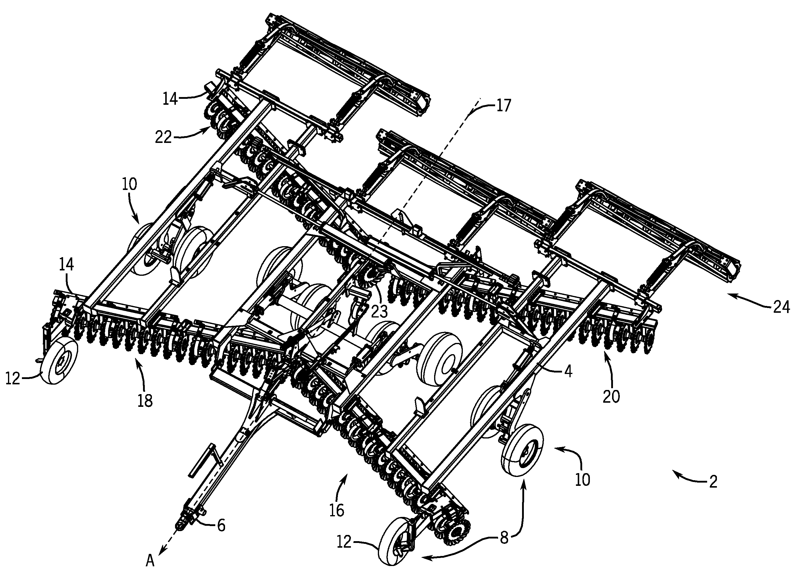
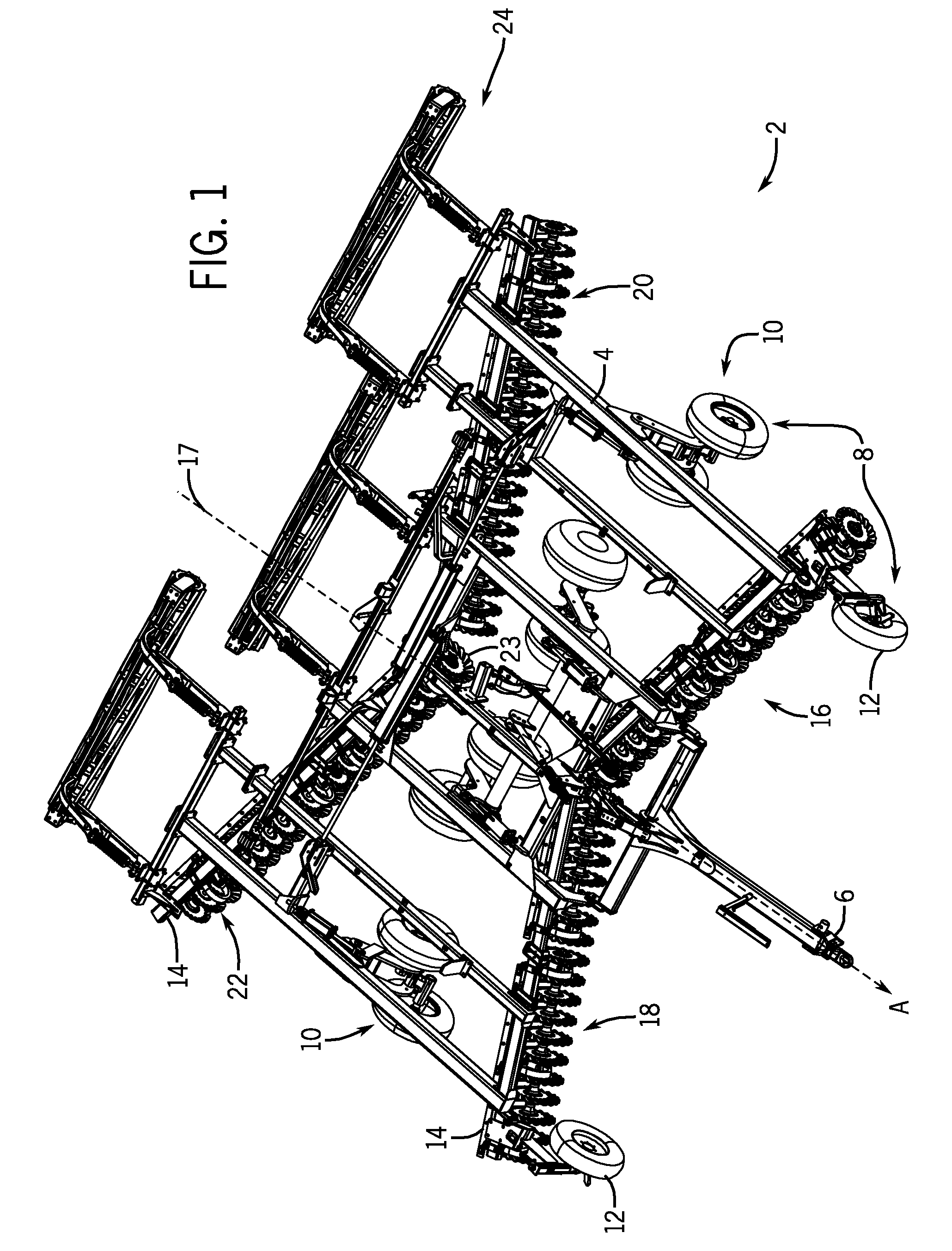
[0039]Referring to FIG. 1, a vertical tilling implement 2 is shown. An agricultural vehicle pulls the vertical tilling implement 2 in a direction of motion A. The vertical tilling implement 2 includes a main frame 4. The main frame 4 has a hitch 6 on the front end that may be used to connect the vertical tilling implement 2 to an agricultural vehicle such as a tractor. Additionally, a set of wheels 8 are connected to the main frame 4. The set of wheels 8 are oriented in a direction that is in general alignment with the direction of motion A. The set of wheels 8 includes a set of center wheels 10 and a set of pivoting wheels 12. The set of center wheels 10 is attached across the main frame 4 at positions, for example, roughly midway between the front and rear ends of the main frame 4. The set of center wheels 10 may include a system for adjusting the distance between the main frame 4 and the set of center wheels 10. This system for adjusting may permit the set of center wheels 10 to ...


PUM

PropertyMeasurementUnit
Angleaaaaaaaaaa
Lengthaaaaaaaaaa
Depthaaaaaaaaaa

Abstract

A vertical tilling implement to be pulled behind and agricultural vehicle having a number of gangs of fluted-concave disc blades, rolling baskets, and wheels connected to a main frame. As the vertical tilling implement is pulled, the fluted-concave disc blades move the soil in a direction lateral to the side of the blades as well as up. Meanwhile, the rolling bars aid in leveling the seedbed and crushing the remaining large pieces of soil. The vertical tilling implement reduces the amount of subsoil compaction and cuts through heavy residue making it ideal for use in the fall or in the spring.

Description

CROSS-REFERENCE TO RELATED APPLICATION[0001]Not applicable.STATEMENT CONCERNING FEDERALLY SPONSORED RESEARCH OR DEVELOPMENT[0002]Not applicable.FIELD OF THE INVENTION[0003]This invention relates to tillage implements and, in particular, to tillage implements utilizing rotary blades.BACKGROUND OF THE INVENTION[0004]It is well known that to attain the best agricultural performance from a piece of land, a farmer must cultivate the soil, typically through a tilling operation. Common tilling operations include plowing, harrowing, and sub-soiling. Modern farmers perform these tilling operations by pulling a tilling implement behind a motorized tractor. Depending on the crop selection and the soil conditions, a farmer may need to perform several tilling operations at different times over a crop cycle to properly cultivate the land to suit the crop choice.[0005]In one type of tilling operation, rows or gangs of discs are pulled through soil at depths between 3 and 6 inches to break up clods...

Claims


Application Information

Patent Timeline
IPC IPC(8): A01B35/16B21K19/00
CPCA01B49/02A01B5/04Y10T29/49448A01B29/048A01B49/027
Inventor KOVACH, MICHAEL GEORGEMEINERS, TRACEY DUANEKNOBLOCH, DEAN ALANKROMMINGA, GAYLEN JAMESSMART, GREGORY S.
Owner BLUE LEAF I P
Why Eureka
Try Eureka