Fuel injector

a fuel injector and fuel technology, applied in the direction of fuel injecting pumps, machines/engines, mechanical equipment, etc., can solve the problem of simultaneous detonation of charges in an uncontrolled manner known as pinking or knocking

Inactive Publication Date: 2009-05-28
DELPHI INT OPERATIONS LUXEMBOURG S A R L
View PDF3 Cites 21 Cited by
  • Summary
  • Abstract
  • Description
  • Claims
  • Application Information

AI Technical Summary

Benefits of technology

[0029]When a first set of outlets is provided, the outer valve member may be operable to control flow of the first fluid from the first delivery chamber to the first set of outlets while the inner valve member remains engaged with the second seating region. In this way, the first fluid can be delivered from the injector without causing delivery of the second fluid.
[0030]Similarly, when a second set of outlets is provided, the inner valve member may be operable to control flow of the second fluid from the second delivery chamber to the second set of outlets while the outer valve member remains engaged with the first seating region, to allow delivery of the second fluid without causing delivery of the first fluid. Optionally, the inner valve member may be coupled to the movement of the outer valve member to control flow of the second fluid from the second delivery chamber through the first and second outlets, to allow both the first and second fuels to be delivered from the injector at the same time.

Problems solved by technology

If the ignition timing in a spark ignition engine is set too early, for example so that ignition occurs before the power stroke begins, the charge may detonate simultaneously in an uncontrolled manner known as pinking or knocking.

Method used


Image

  • Fuel injector
  • Fuel injector
  • Fuel injector

Examples


first embodiment

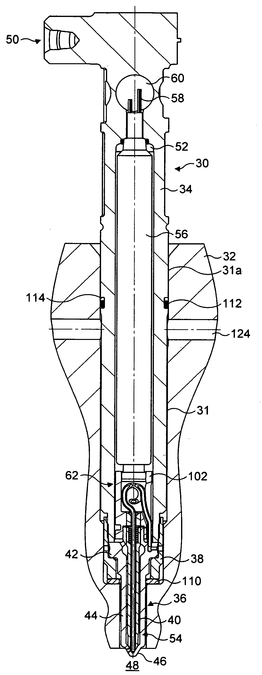
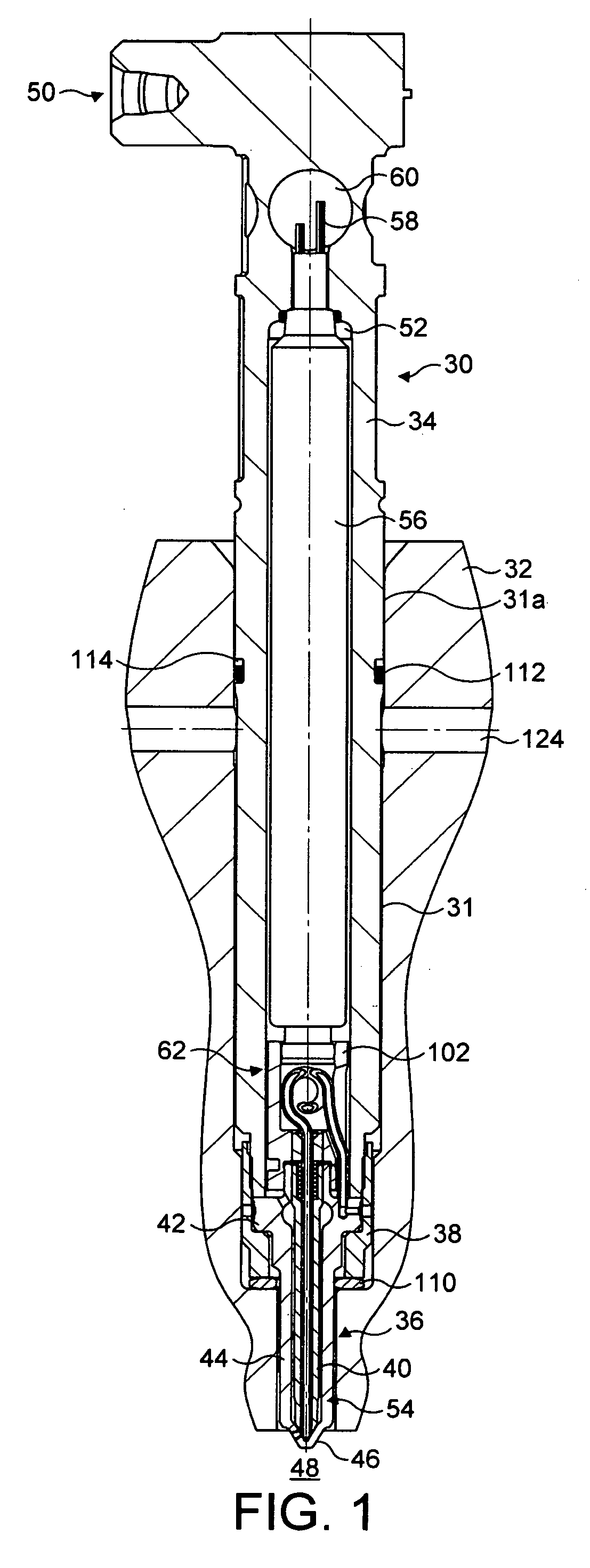
[0103]FIG. 1 shows a fuel injector 30 according to the present invention, mounted in a bore 31 extending through a cylinder head 32 of an internal combustion engine. The injector 30 includes a longitudinally-extending injector body 34 and an injector nozzle 36.

[0104]The injector nozzle 36 is secured to the injector body 34 by means of a capnut 38. The capnut 38 carries internal threads (not shown in FIG. 1) to mate with external threads (not shown) provided on the lower end of the injector body 34. The injector nozzle 36 includes an elongate nozzle body 40 comprising a collar portion 42 of relatively large outside diameter, and a longitudinal portion 44 of relatively small outside diameter.

[0105]The nozzle body 40 also includes a tip region 46 that extends beyond a lower surface of the cylinder head 32 and into a combustion chamber 48 of the cylinder. The fuel injector 30 is supplied with first and second fluids, referred to hereafter as first and second fuels, from respective first...

second embodiment

[0150]FIGS. 5a and 5b show part of a fuel injector 30a according to the invention wherein the second set of outlets in the nozzle body 40a comprises a single downwards-pointing orifice or outlet at the tip of the nozzle, known hereafter as the second outlet 82a. The second outlet is aligned axially with the nozzle body 40a. The inner valve member 76a is provided with passages 160 extending from the outer surface to the inner surface of the inner valve member 76a and arranged between the upper and lower seating lines 152a, 152b of the inner valve member 76a.

[0151]In the intermediate energization state, the inner valve member 76a is seated on the second seating region 100b as shown most clearly in FIG. 5b. Cooperation of the upper seating line 152a of the inner valve member 76a with the second seating region 100b prevents the second fuel from flowing from the second delivery chamber 142a within the bore of the inner valve member 76a toward the first set of outlets 80, particularly wh...

third embodiment

[0154]FIGS. 7a and 7b show a fuel injector 30b according to the present invention that provides an alternative communication path for the second fuel. In this embodiment, no passages for the second fuel are provided in the capnut 38b or the nozzle body 34b of the injector 30b and the second fuel need not be routed through the cylinder head (not shown in FIGS. 7a and 7b). Instead, the coiled portion 116b of the inner valve member 76b comprises a single loop, and the upstream portion 118b of the inner valve member 76b emerges from the coiled portion 116b in an upwardly direction. The coiled portion 116b is accommodated partly within the cavity 106b of the piston member 102b, and partly within an aperture 120b in the wall of the piston member 102b, so that the upstream portion 118b of the inner valve member 76b emerges upwardly from the coiled portion 116b alongside the piston member 102b and in a direction parallel to the longitudinal direction of the injector 30b.

[0155]In this embod...


PUM


Abstract

A fuel injector for use in an internal combustion engine, comprising a nozzle body being provided with a nozzle bore and at least one set of one or more outlets for fluid, an outer valve member received within the nozzle bore and being engageable with a first seating region of the nozzle body to control the flow of a first fluid from a first delivery chamber, the outer valve member being provided with an outer valve bore, and an inner valve member received within the outer valve bore and being engageable with a second seating region of the nozzle body to control the flow of a second fluid from a second delivery chamber. In various embodiments, the fuel injector can be arranged to allow the first and second fluids to be injected separately and/or together. In one embodiment, the first and second fluids can be mixed within the injector before injection.

Description

TECHNICAL FIELD[0001]The present invention relates to a fuel injector for use in a fuel injection system for an internal combustion engine. More particularly, the present invention relates to a fuel injector wherein first and second valve needles are operable to control the injection of two fluids into a combustion space.BACKGROUND OF THE INVENTION[0002]Modern internal combustion engines typically operate either on the spark ignition principle, or on the compression ignition principle. In both cases, reciprocating pistons undergo a combustion cycle comprising intake, compression, power and exhaust strokes within respective cylinders of the engine. The reciprocating motion of the piston is driven on the power stroke by the rapid expansion of combusting gases within a combustion chamber of the cylinder.SUMMARY OF THE INVENTION[0003]In a spark ignition engine, such as a gasoline or petrol engine, a mixture of fuel and air, known as a charge, is introduced into the combustion chamber on...

Claims


Application Information

Patent Timeline
Patent Type & Authority Applications(United States)
IPC IPC(8): F02M61/04
CPCF02B1/12F02D19/0694F02D19/08F02D19/081F02M43/04F02M45/086F02M51/0603F02M61/042F02M61/182F02M2200/21F02M2200/46F02M2200/703Y02T10/36F02D19/061F02D19/0642F02D19/0657F02B3/06Y02T10/30
Inventor COOKE, MICHAEL PETERGREEVES, GODFREYMILOVANOVIC, NEBOJSA
Owner DELPHI INT OPERATIONS LUXEMBOURG S A R L
Why Eureka
Try Eureka