Light emitting element and method for producing the same

a technology light sources, applied in the direction of discharge tube luminescnet screens, spark plugs, lighting and heating apparatus, etc., can solve the problems of insufficient adjustment of chromaticity, low light extraction efficiency of light emitting elements, and decreased chromaticity variation, so as to achieve the effect of adjusting the chromaticity variation of light emitted

Inactive Publication Date: 2009-05-28
SHARP KK
View PDF6 Cites 30 Cited by
  • Summary
  • Abstract
  • Description
  • Claims
  • Application Information

AI Technical Summary

Benefits of technology

[0015]As described above, in the present invention, it is possible to adjust a chromaticity variation in light emitted from the light emitting elements by controlling, with the light scattering s

Problems solved by technology

However, the white light emitting element still has a problem in that its chromaticity widely varies compared to the fluorescent bulb, the cold-cathode tube, and the like, and therefore is required to have a chromaticity variation decreased to the same extent as the fluorescent bulb and the cold-cathode tube.
Consequently, the light emitting element has a low light extraction efficiency.
If the resin is arranged so as to be thinner in thickness for the purpose of preventing a decrease in the light extraction efficiency, it becomes impossible to adjust the chromaticity to a sufficient extent.
On the other hand, if the resin is arra

Method used


Image

  • Light emitting element and method for producing the same
  • Light emitting element and method for producing the same
  • Light emitting element and method for producing the same

Examples


first embodiment

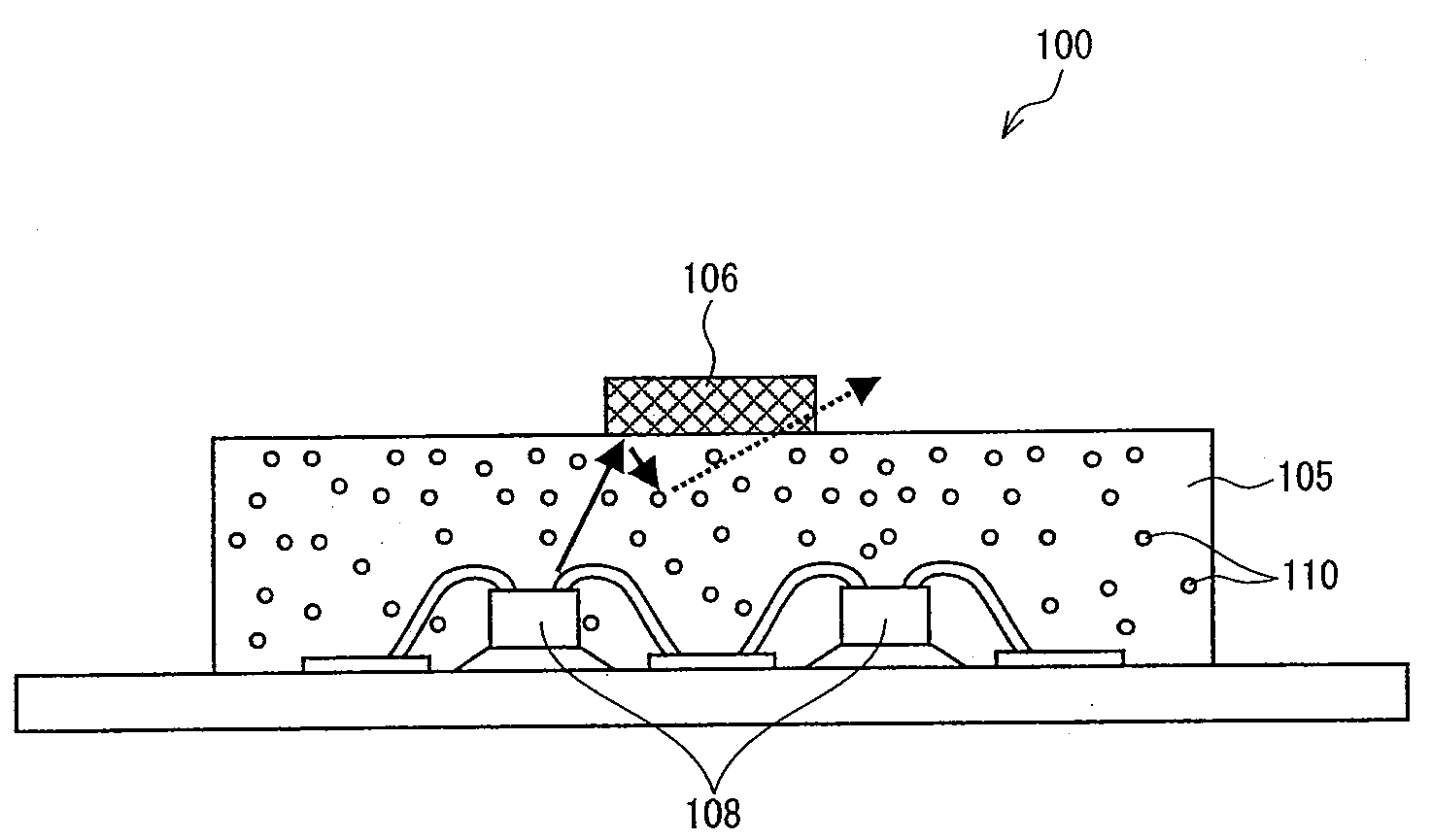
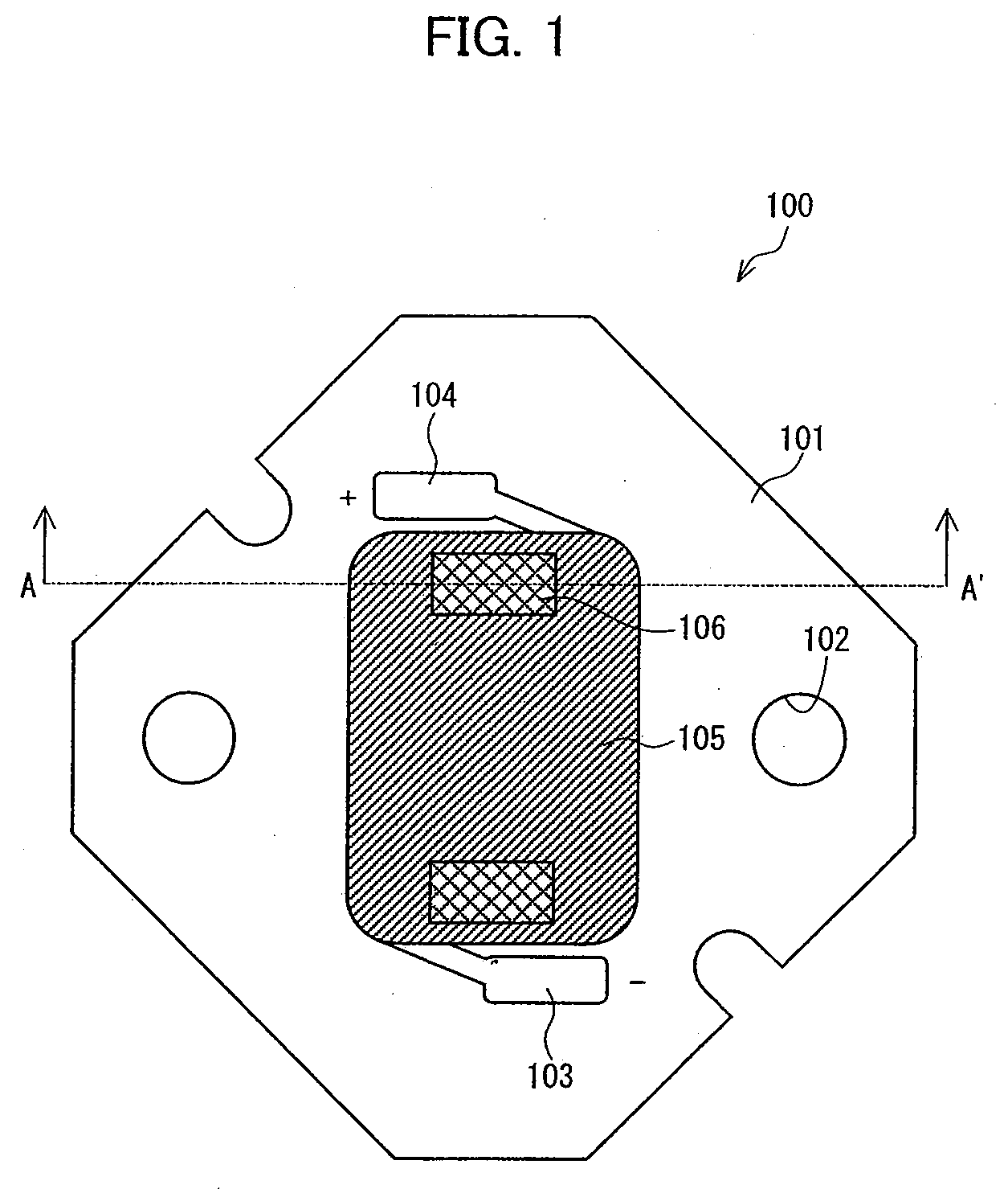
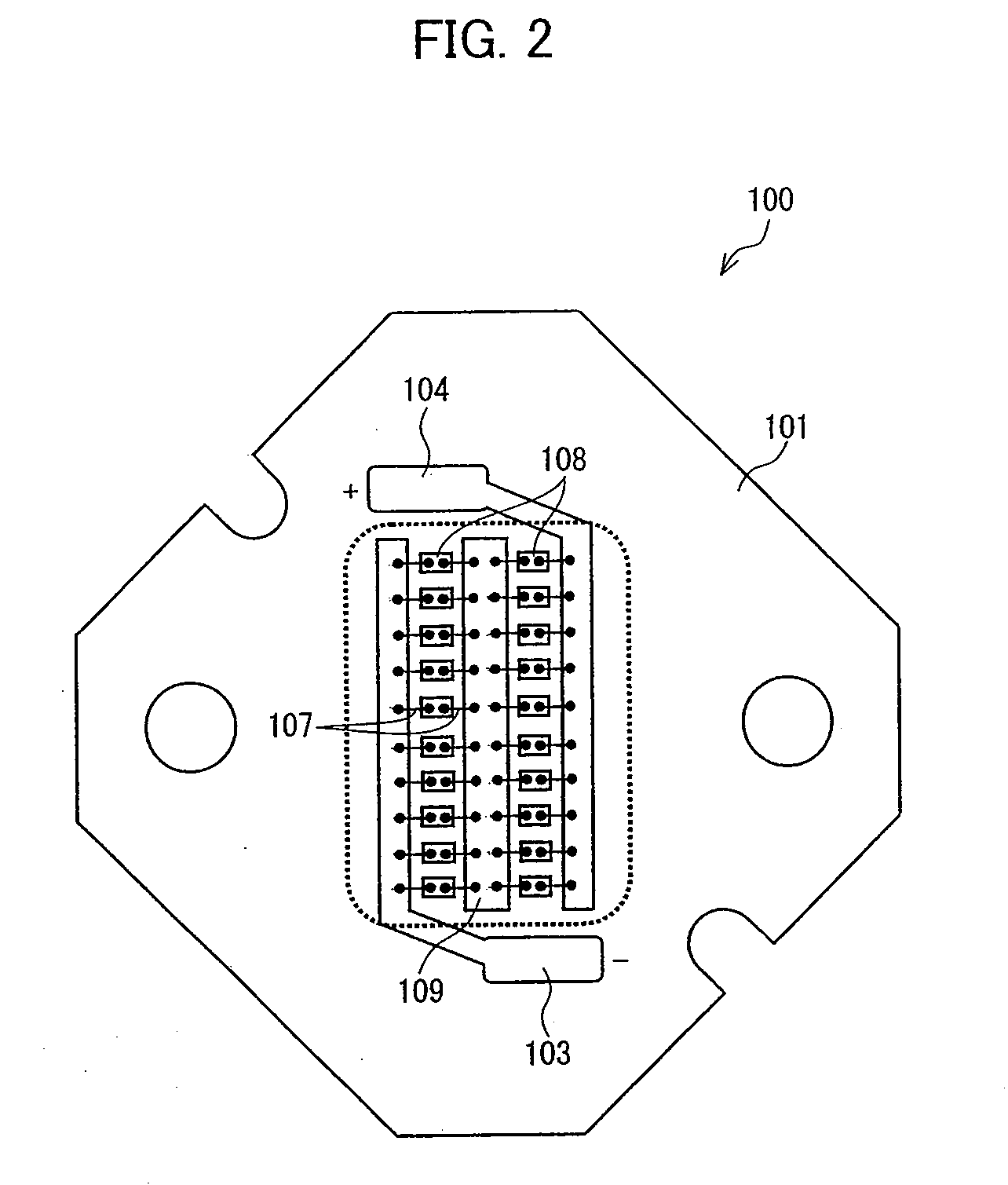
[0028]One embodiment of the light emitting element in accordance with the present invention is described below with reference to FIGS. 1 through 4. FIG. 1 is a top view of a light emitting element 100 in accordance with one embodiment of the present invention. FIG. 2 is a top view showing an inside of the light emitting element 100 shown in FIG. 1. FIG. 3 is a view showing a cross-section across line A-A′ in the light emitting element 100 shown in FIG. 1. FIG. 4 is a chromaticity diagram showing a chromaticity variation among the light emitting elements 100 shown in FIG. 1.

[0029]As shown in FIGS. 1 through 3, the light emitting element 100 has a substrate 101, mounting holes 102, a negative electrode pattern 103, a positive electrode pattern 104, a sealing resin section (a first resin section) 105, light scattering resin sections (second resin sections) 106, metal wires 107, light emitting diode chips 108, and an electrode pattern 109. The sealing resin section 105 is made of an opt...

second embodiment

[0046]Another embodiment of the light emitting element in accordance with the present invention is described below with reference to FIGS. 5 through 7. FIG. 5 is a cross-sectional view of a light emitting element 200 in accordance with one embodiment of the present invention. FIG. 6 is a top view showing an inside of the light emitting element 200 shown in FIG. 5. FIG. 7 is a chromaticity diagram showing a chromaticity variation among the light emitting elements 200 shown in FIG. 5. Note that a specific explanation of the same member and structure as the first embodiment is omitted in the present embodiment.

[0047]As shown in FIGS. 5 and 6, the light emitting element 200 has a positive electrode section 201, a negative electrode section 202, a light emitting diode chip 203, a resin paste 204, metal wires 205, a resin mounting section 206, a reflector section 207, a sealing resin section 208, fluorescent bodies 209, and a light scattering resin section 210. The fluorescent bodies 209 ...

third embodiment

[0063]Still another embodiment of the light emitting element in accordance with the present invention is described below with reference to FIGS. 10 and 11. FIGS. 10 and 11 are schematic views showing a part of processes for forming light emitting elements 500 and 600 in accordance with the present invention, respectively. The present embodiment includes the same arrangement as the first embodiment, except the light scattering section.

[0064]As shown in FIG. 10, a surface of a sealing resin section 502 of a light emitting element 500 is ground by a disc-shaped grinding stone 501 having a grinding material made of alumina, thereby forming a light scattering section 504 having a rough-surfaced shape. The rough surface is formed so as to have a size that is at least same as the wavelength of visible light so that light can be effectively scattered. Further, a surface roughness Ra of the rough-surfaced shape formed in response to the chromaticity distribution of the light emitting element...


PUM


Abstract

A light scattering section is formed on at least part of a surface of a sealing resin section including fluorescent bodies and covering light emitting diode chips. Light from the light emitting diode chips is scattered by the light scattering section, and then is returned to the sealing resin section so as to excite the fluorescent bodies so that fluorescence is generated. Part of the light to be emitted outside a light emitting element from the light emitting diode chips returns to the sealing resin section so that chromaticity of the light is converted by the fluorescent bodies, thereby adjusting a chromaticity variation among the light emitting elements. In this way, the chromaticity variation among the light emitting elements can be adjusted.

Description

[0001]This Nonprovisional application claims priority under U.S.C. §119(a) on Patent Application No. 306633 / 2007 filed in Japan on Nov. 27, 2007, the entire contents of which are hereby incorporated by reference.FIELD OF THE INVENTION[0002]The present invention relates to a light emitting element including a light emitting diode chip and a resin section for covering the light emitting diode chips and containing fluorescent bodies that are excitable by light from the light emitting diode chip.BACKGROUND OF THE INVENTION[0003]A white light emitting element using a semiconductor light emitting element is expected to be applicable to market of bulb or tube-shaped lighting devices of the next generation such as an electric bulb used in a general lighting apparatus, a liquid crystal backlight, a fluorescent tube, a cold-cathode tube, and the like. Such a white light emitting element includes a light emitting diode chip covered with a resin or the like in which a fluorescent body is contai...

Claims


Application Information

Patent Timeline
IPC IPC(8): H01J1/62H05B33/10H01L33/50H01L33/54H01L33/56H01L33/62
CPCH01L25/0753H01L2224/45144H01L33/56H01L2224/48091H01L2224/73265H01L2933/0091H01L33/50H01L2924/1815H01L2924/01019H01L2224/48247H01L2224/48227H01L2224/32245H01L2224/32225H01L2924/00014H01L2924/00H01L2924/00012H01L24/73H01L2924/181
Inventor MORIOKA, TATSUYA
Owner SHARP KK
Why Eureka
Try Eureka