
Circular self-powered magnetic generator

Inactive Publication Date: 2009-05-28
RAGHUPRASAD PUTHALATH KOROTH
View PDF9 Cites 82 Cited by
  • Summary
  • Abstract
  • Description
  • Claims
  • Application Information

AI Technical Summary

Benefits of technology

[0013]In another embodiment, the entire ring portion of the system will be evacuated of any air; this helps reduce air resistance, friction and inertia dramatically. Alternatively, this device can be used in space in the absence of gravity wherein the permanent magnet and all of the mechanisms are within a housing such that the movement can be created and repeated in such a zero gravity environment. The moving permanent magnets simply rely on the attractive or repulsive magnetic forces or combinations of both to provide movement and power generation. It is believed that this method of charging a battery can be used in combination with other devices such as storage batteries, solar or wind to provide a means to constantly generate electricity to assist as a supply source for electricity. The objective is to use a minimal amount of electromagnetic force at each electromagnet requiring minimal use of electricity and that the activating means should be of minimal electricity consumption such that the power generated exceeds the amount of energy consumed in such a fashion that the battery can be charged or create excess electricity for other purposes. It is understood that frictional losses and other losses can be accumulated such that in the end the device will need to have the battery recharged at some period. However, the expectation of battery charging is such that the inventor anticipates the battery can provide many times the normal amount of time to provide a constant working of the power generation apparatus so the battery is continuously being recharged by the power generated in the device.
[0014]It is anticipated that the electricity generated in the central core will itself help re-magnetize the moving permanent magnet by the appropriate direction of the windings in central coil. This will eliminate the need to replace or re-magnetize the magnet at required intervals. This continuous process of re-magnetizing eliminates the interruption of the generation of electricity.

Problems solved by technology

The biggest problem with such devices is that the source of energy is not always constant.
Water flows, wind and solar energy often times are not predictable and, in the case of solar power it is not available during the night.

Method used


Image

  • Circular self-powered magnetic generator
  • Circular self-powered magnetic generator
  • Circular self-powered magnetic generator

Examples


Embodiment Construction

[0026]The following language is of the best presently contemplated mode or modes of carrying out the invention. This description is made for the purpose of illustrating the general principles of the invention and should not be taken in a limiting sense. The scope of the invention is best determined by reference to the appended claims. The reference numerals as depicted in the drawings are the same as those referred to in the specification. For purposes of this application, the various embodiments illustrated in the figures each use the same reference numeral for similar components. The structures employ basically the same components with variations in location or quantity thereby giving rise to the alternative constructions in which the inventive concept can be practiced.

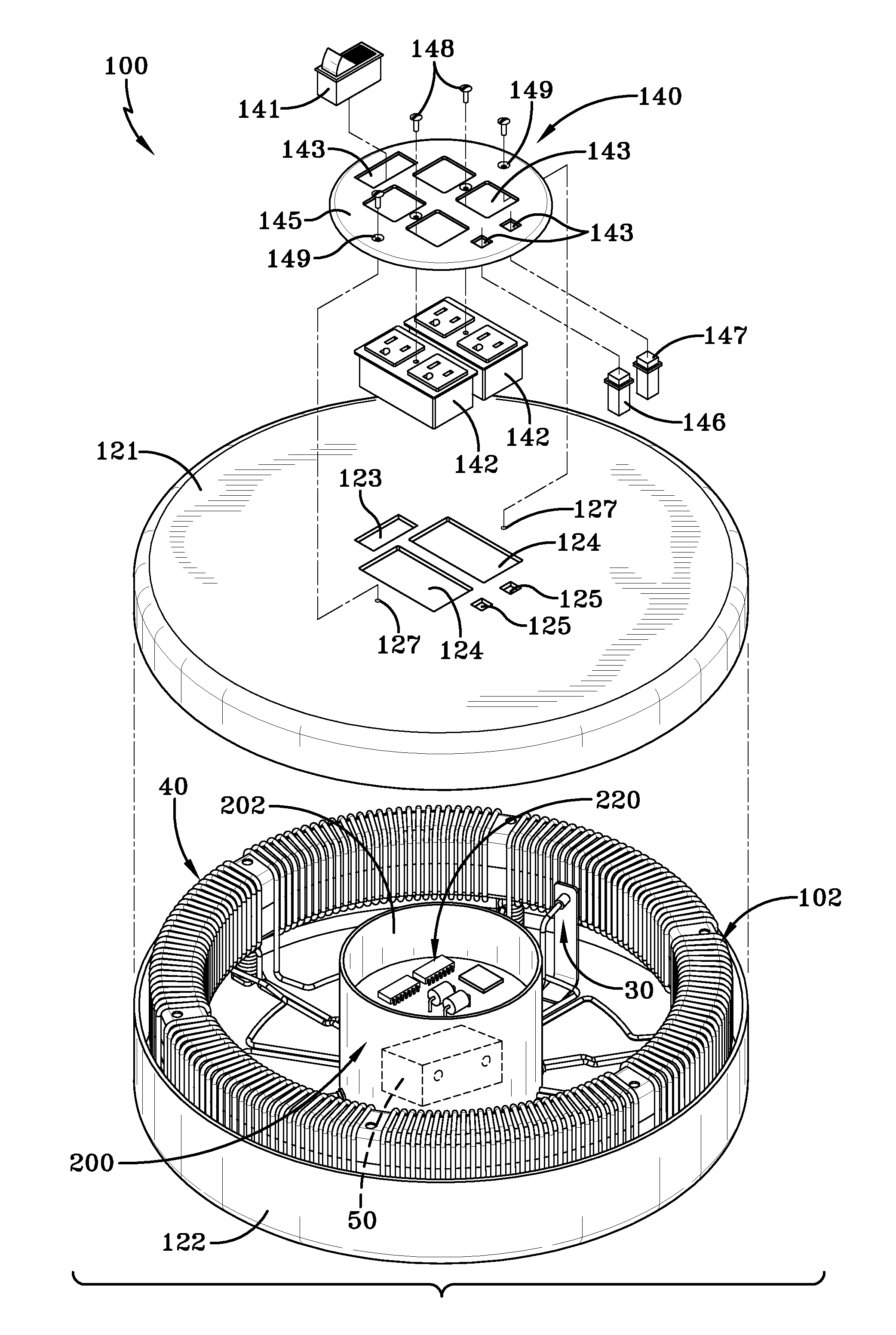
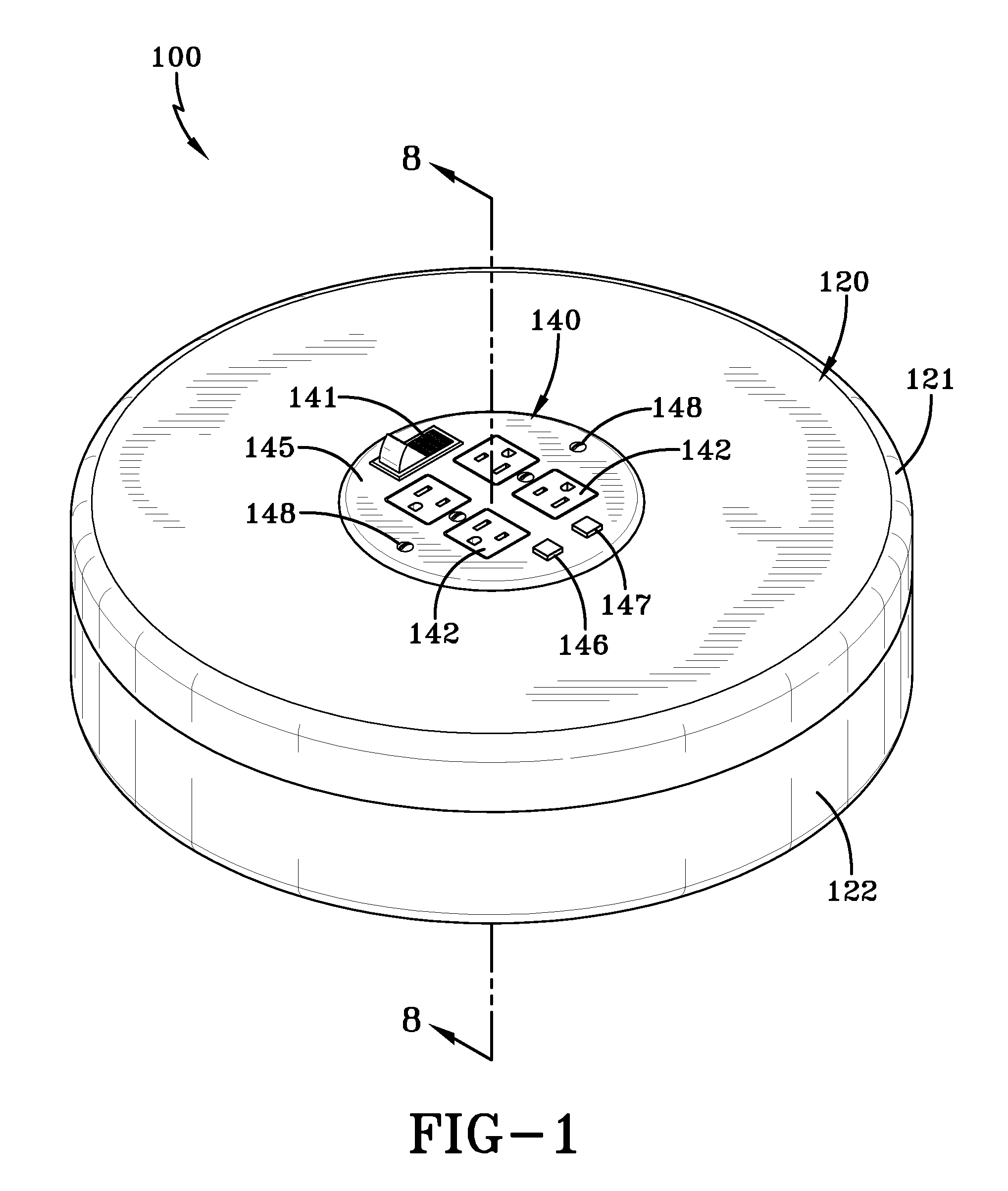
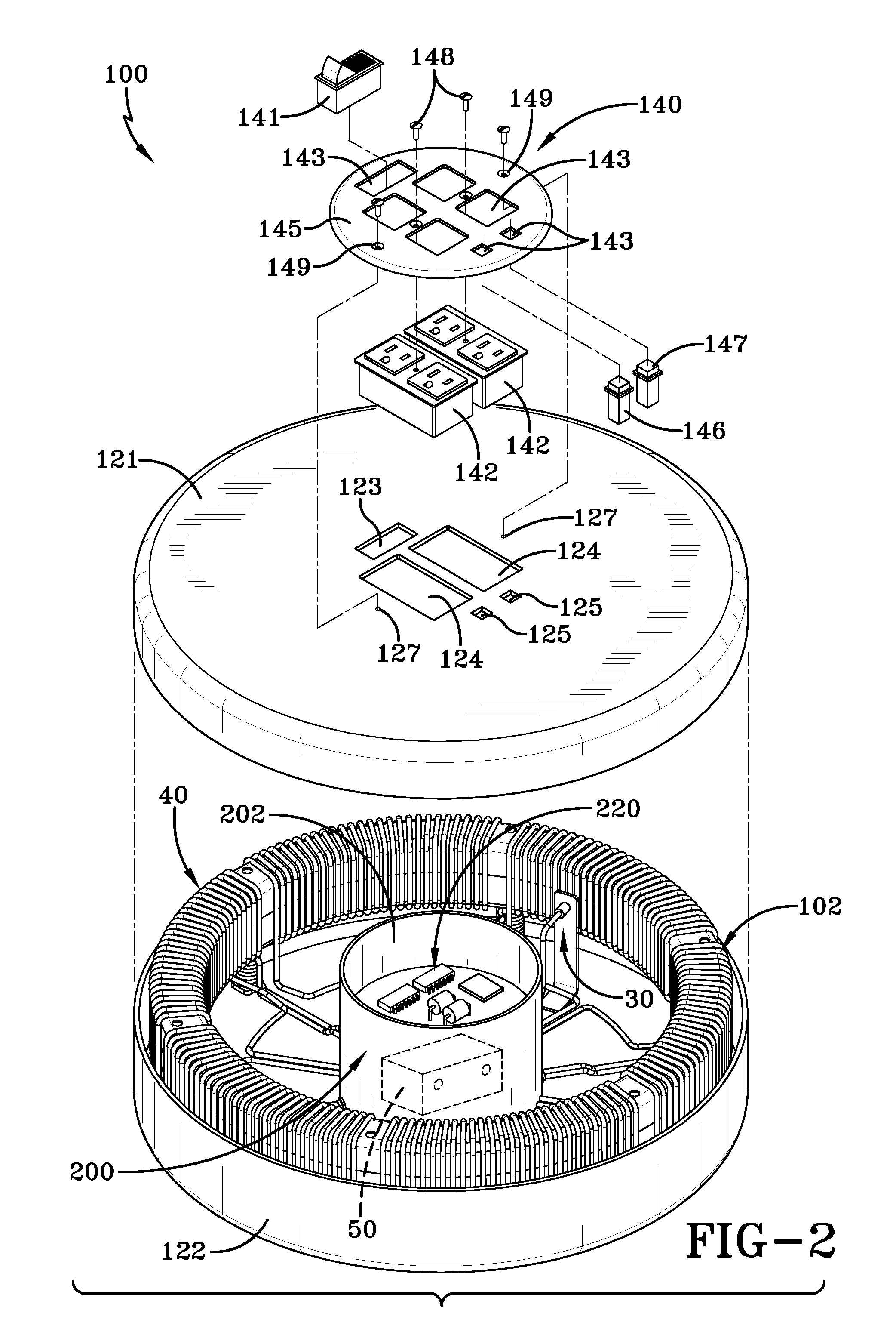
[0027]A circular self-powered magnetic generator apparatus 100 of an exemplary embodiment of the invention is illustrated in FIGS. 1-10. As shown in FIG. 1, the circular generator apparatus 100 has an external housi...


PUM


Abstract

An improved power generation apparatus 100 has one or more moving permanent magnets 10, the rapid movement of the one or more permanent magnets 10 successively switches on and off the different electromagnets 20 in sequence to pull the one or more magnets 10 in a circular motion. This circular movement of the one or more magnets 10 generates an electric current in each central coil 40 to power the activating means 30 and to charge the battery 50 for storage or any excess electricity generated can be used to power other devices. Alternatively, as described in a second embodiment, the electromagnets 20 can be switched on when the same polarity of the one or more permanent magnets 10 pass to create a repulsive force which pushes the one or more permanent magnets 10 along the guide means 2 to propel the permanent magnets 10.

Description

TECHNICAL FIELD[0001]The present invention relates to an apparatus that generates electric currents through a plurality of coils to power or charge a battery using one or more moving permanent magnets and electro-magnetic coils. Power generation is self-sufficient i.e. no external power sources are needed.BACKGROUND OF THE INVENTION[0002]The ability to generate an electric current by passing a magnet through a coil of electrically conductive wires is well known, and commonly referred to as the Michael Faraday experiment.[0003]The use of wires wound around a rotating bank of magnets is a common practice in the manufacture of electric motors and electric power generators.[0004]It has long been a goal to use naturally occurring mechanical power to generate electricity. Hydraulic generation of power uses water flows to turn turbines; wave's motion has been suggested to generate electricity; new wind driven propellers are now making electricity and solar energy can be captured and conver...

Claims


Application Information

Patent Timeline
IPC IPC(8): H02J7/14H02K53/00
CPCH02K53/00H02J7/32
Inventor RAGHUPRASAD, PUTHALATH KOROTH
Owner RAGHUPRASAD PUTHALATH KOROTH
Learn More