Zero-delay buffer with common-mode equalizer for input and feedback differential clocks into a phase-locked loop (PLL)

a phase-locked loop and buffer technology, applied in the field of clock buffers, can solve the problems of disrupting system operation, large system may require many clock signals, and system operation at blazingly fast speeds

Active Publication Date: 2009-05-28
HONG KONG APPLIED SCI & TECH RES INST
View PDF9 Cites 19 Cited by
  • Summary
  • Abstract
  • Description
  • Claims
  • Application Information

AI Technical Summary

Problems solved by technology

Large systems may require many clock signals that are applied to large loads.
However, today's modern systems operate at blazingly fast speeds, and the single-ended clocks have too many signal distortions that can disrupt system operation.
Any external interference tends to couple in equally to both physical wires of a differential clock, so the interference tends to cancel out.

Method used


Image

  • Zero-delay buffer with common-mode equalizer for input and feedback differential clocks into a phase-locked loop (PLL)
  • Zero-delay buffer with common-mode equalizer for input and feedback differential clocks into a phase-locked loop (PLL)
  • Zero-delay buffer with common-mode equalizer for input and feedback differential clocks into a phase-locked loop (PLL)

Examples


Embodiment Construction

[0018]The present invention relates to an improvement in differential zero-delay clock generators. The following description is presented to enable one of ordinary skill in the art to make and use the invention as provided in the context of a particular application and its requirements. Various modifications to the preferred embodiment will be apparent to those with skill in the art, and the general principles defined herein may be applied to other embodiments. Therefore, the present invention is not intended to be limited to the particular embodiments shown and described, but is to be accorded the widest scope consistent with the principles and novel features herein disclosed.

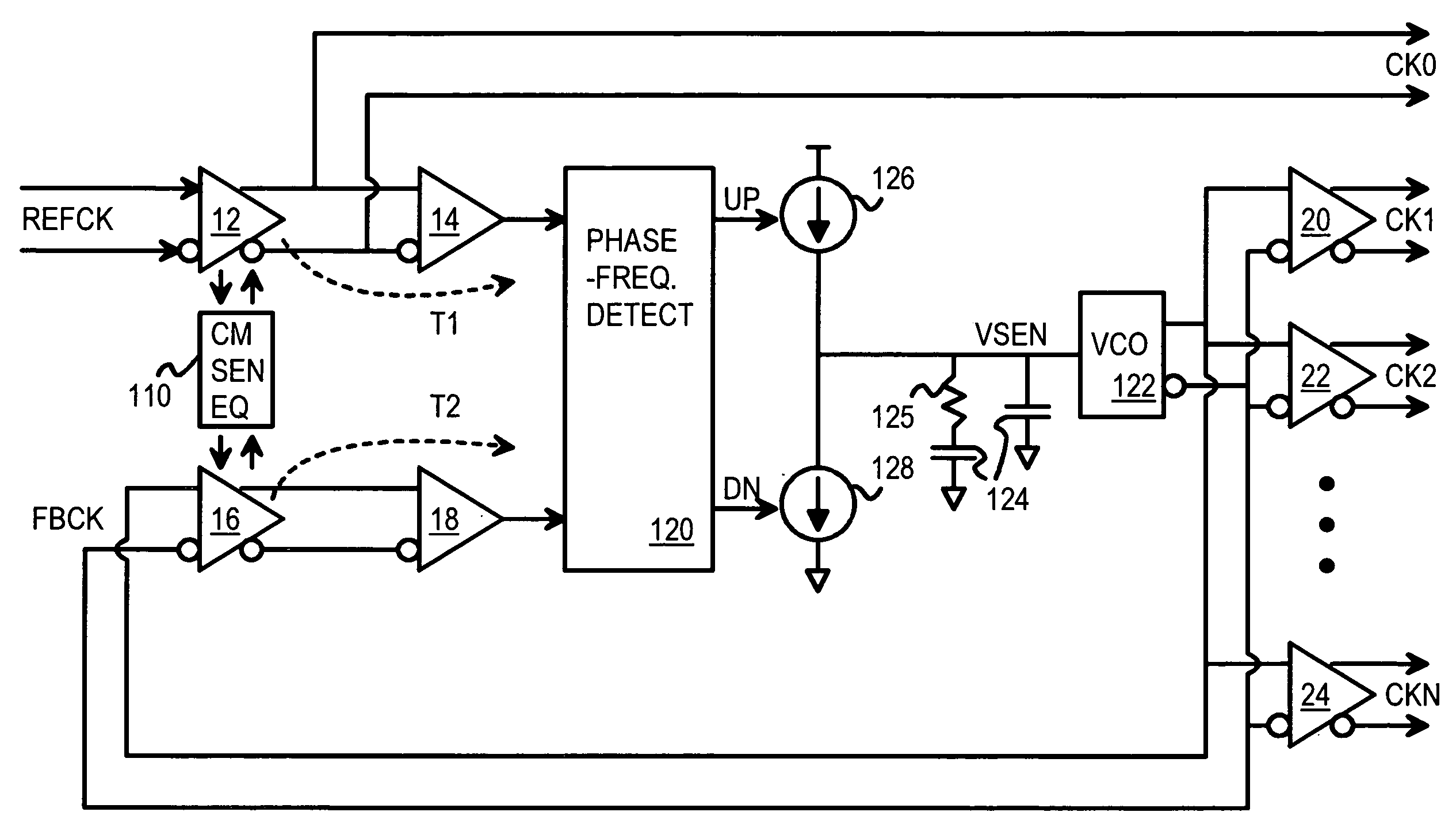
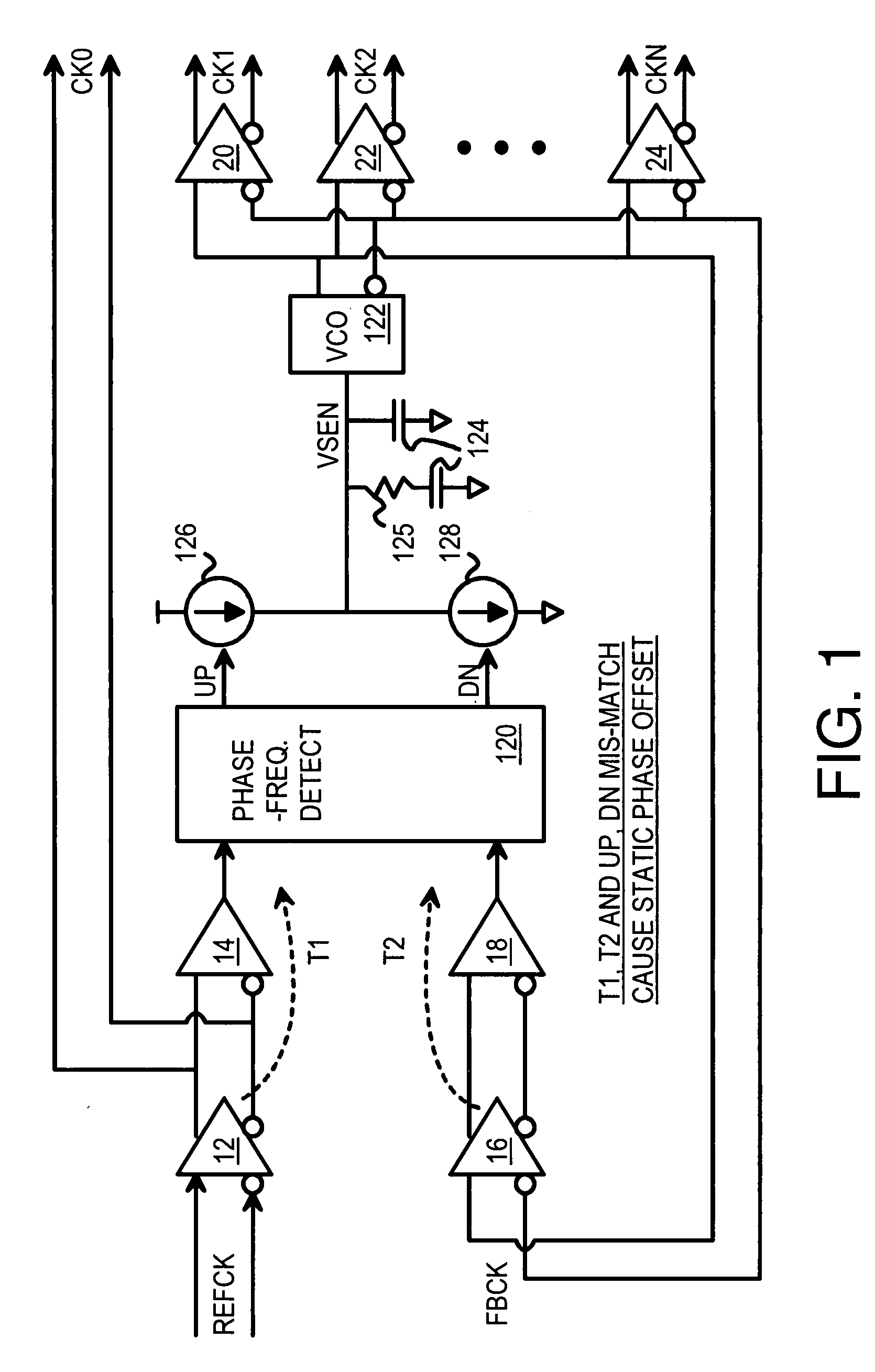
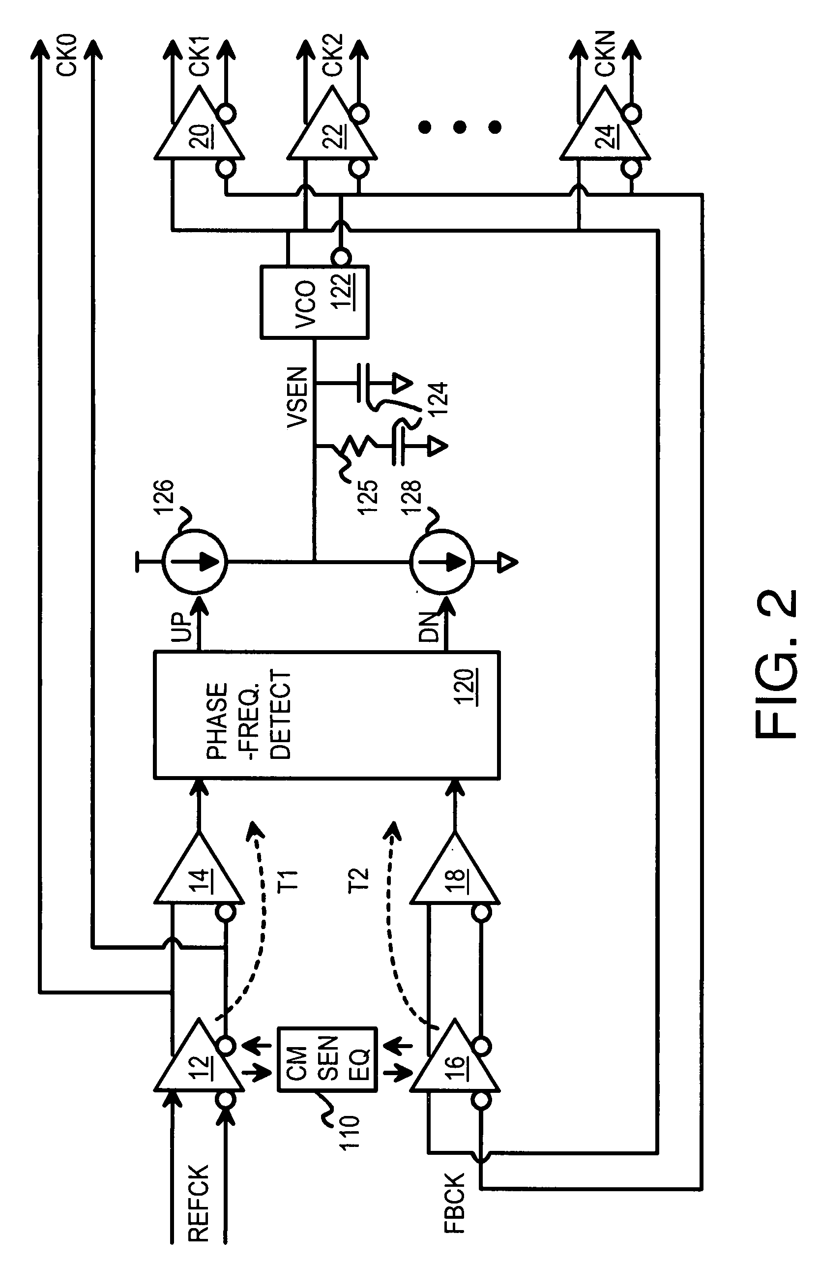
[0019]The inventors have realized that differential clocks can be generated with a zero-delay clock generator. However, common-mode voltage drift is a problem. Both physical wires carrying a differential clock have a static voltage known as the common-mode voltage. The clock signal is a small alternating signa...


PUM


Abstract

A zero-delay clock generator has a phase-locked loop (PLL) that generates a feedback clock and receives a reference clocks. All clocks are differential and have a common-mode voltage. The common-mode voltage of an externally-generated reference clock can vary from the common-mode voltage of the internally-generated feedback clock. Differences in common-mode voltage of the reference clock and feedback clock cause delay variations resulting in static phase offsets of generated clocks. A common-mode sense and equalizer senses the common-mode voltages of the buffered reference and feedback clocks, and generates control voltages. The control voltages adjust the common-mode voltage and delay of differential buffers that receive the reference and feedback clocks. The control voltages adjust the differential buffers to match the common-mode voltages of the buffered reference and feedback clocks. The buffered clocks are then applied to a phase and frequency detector of the PLL.

Description

FIELD OF THE INVENTION[0001]This invention relates to clock buffers, and more particularly to zero-delay phase-locked loop (PLL) clock buffers.BACKGROUND OF THE INVENTION[0002]Large digital electronic systems have many blocks of circuits that must communicate with each other. Communication is facilitated by the use of clocks that synchronize data transfers. Large systems may require many clock signals that are applied to large loads. These clocks are often synchronized to each other during clock generation. Higher operating speeds required that these clocks be accurate and precise.[0003]Phase-locked loops (PLL's) are used to receive an external clock and to clean up any jitter or other signal distortions. In a PLL, an input clock is compared to a feedback clock that is generated by the PLL, and the feedback clock is altered by the PLL to match the input clock in phase and frequency.[0004]One kind of clock generator that uses a PLL is known as a zero-delay buffer. Many clocks are gen...

Claims


Application Information

Patent Timeline
Patent Type & Authority Applications(United States)
IPC IPC(8): H03L7/089H03L7/085H03K3/00
CPCH03L7/0891H03L7/081
Inventor KWONG KWOK KUEN (DAVID)WAN HO MING (KAREN)
Owner HONG KONG APPLIED SCI & TECH RES INST
Why Eureka
Try Eureka