Divided clock synchronization

a technology of divided clocks and clocks, applied in the direction of pulse automatic control, pulse manipulation, pulse technique, etc., can solve the problems of large quantities of digital data generated, transmitted, collected, processed, stored, etc., and the cost of inexpensive 8:64 demultiplexers may not be commercially availabl

Active Publication Date: 2011-10-11
THE BOEING CO
View PDF5 Cites 11 Cited by
  • Summary
  • Abstract
  • Description
  • Claims
  • Application Information

AI Technical Summary

Problems solved by technology

The continued development and proliferation of digital technology results in large quantities of digital data being generated, transmitted, collected, processed, and stored.
However, demultiplexing the digital data stream presents its own problems.
However, inexpensive 8:64 demultiplexers generally may not be commercially available.
Further, an 8:64 demultiplexer is a relatively high density device and relatively few 8:64 demultiplexers may be manufactured on a single wafer which may lead to wafer yield concerns.
Although an 8:64 demultiplexer may be replaced by an array of individual demultiplexers, such as an array of four parallel 2:16 demultiplexers or an array of eight parallel 1:8 demultiplexers, a problem remains in synchronizing the individual demultiplexers.
As a result, the individual demultiplexers may start up with their respective clock dividers in different states, resulting in the output of the different individual demultiplexers being out of synchronization and potentially causing misalignment of the deserialized data bits in the output.
However, applying an accurately synchronized input to each of a plurality clock inputs may be difficult.
Further, if a clock reset input fails to properly reset a clock divider or if the clock reset signal is not accurately and simultaneously applied to each of the devices, the devices may remain desynchronized as long as the devices remain powered on.

Method used


Image

  • Divided clock synchronization
  • Divided clock synchronization
  • Divided clock synchronization

Examples


Embodiment Construction

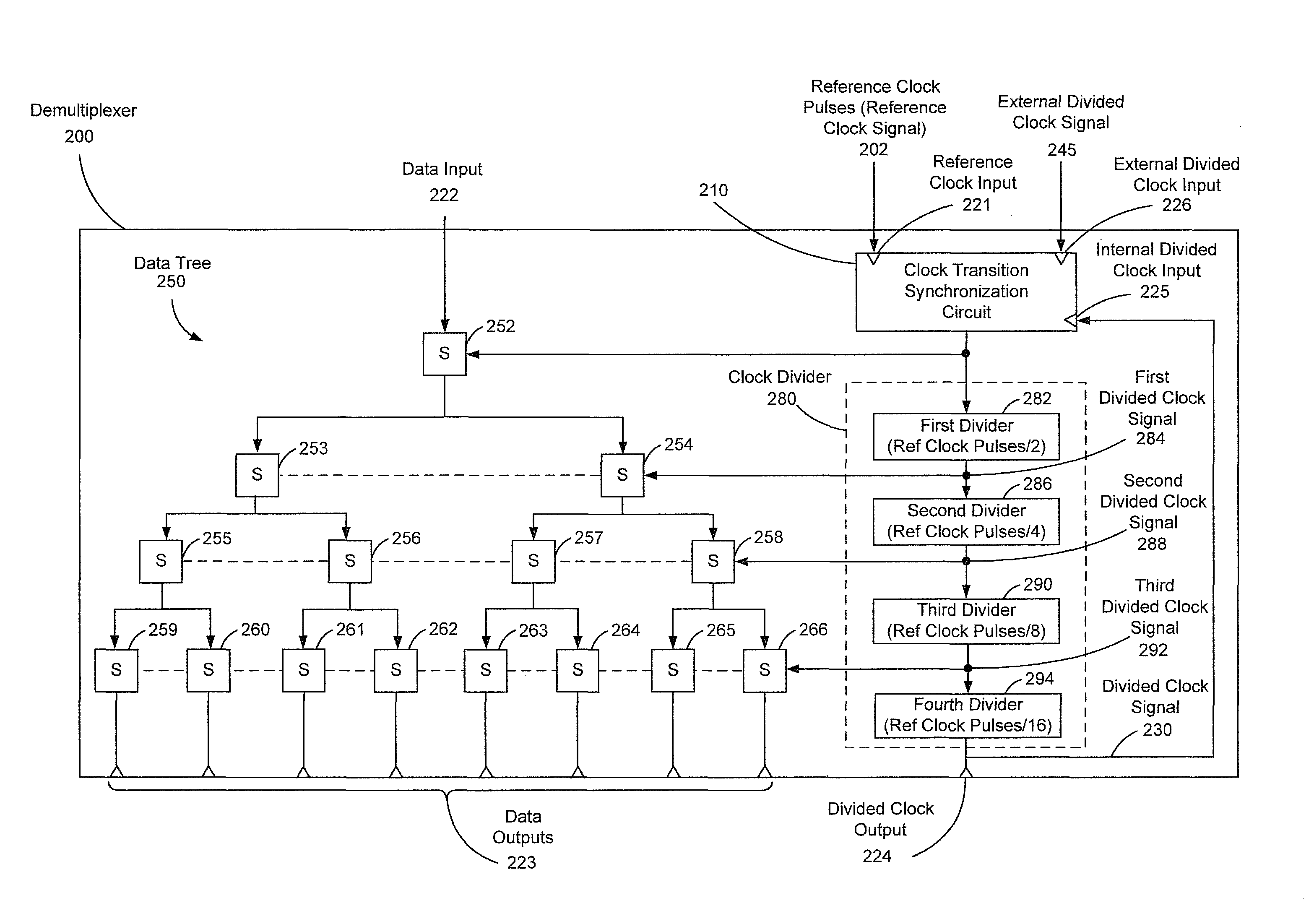
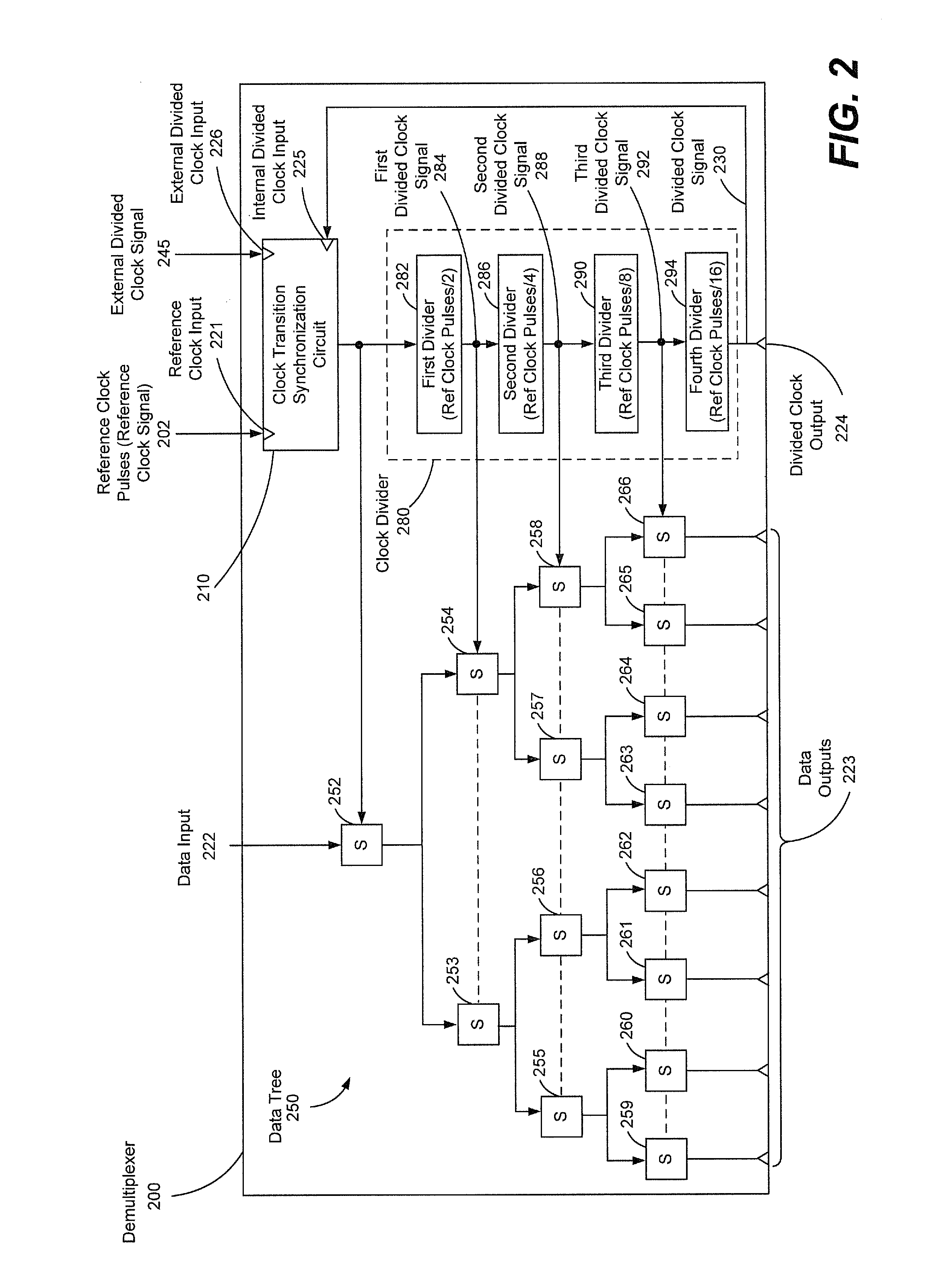
When a plurality of devices, such as demultiplexers or other digital devices, are arranged in parallel to deserialize a digital data stream, data output by the parallel devices may be synchronized so that the deserialized data is not misaligned. When demultiplexers or other digital devices are powered on, the devices may start up in different states. Embodiments of the present disclosure synchronize divided clock signals by monitoring when a divided clock signal output by a slave device transitions between clock states out of synchronization with a master divided clock signal output of a master device. When the divided clock signal transitions between clock states out of synchronization, at least one of the reference clock pulses that drive the divided clock signal in the slave device is suppressed until the divided clock signal transitions in synchronization with the master divided clock signal.

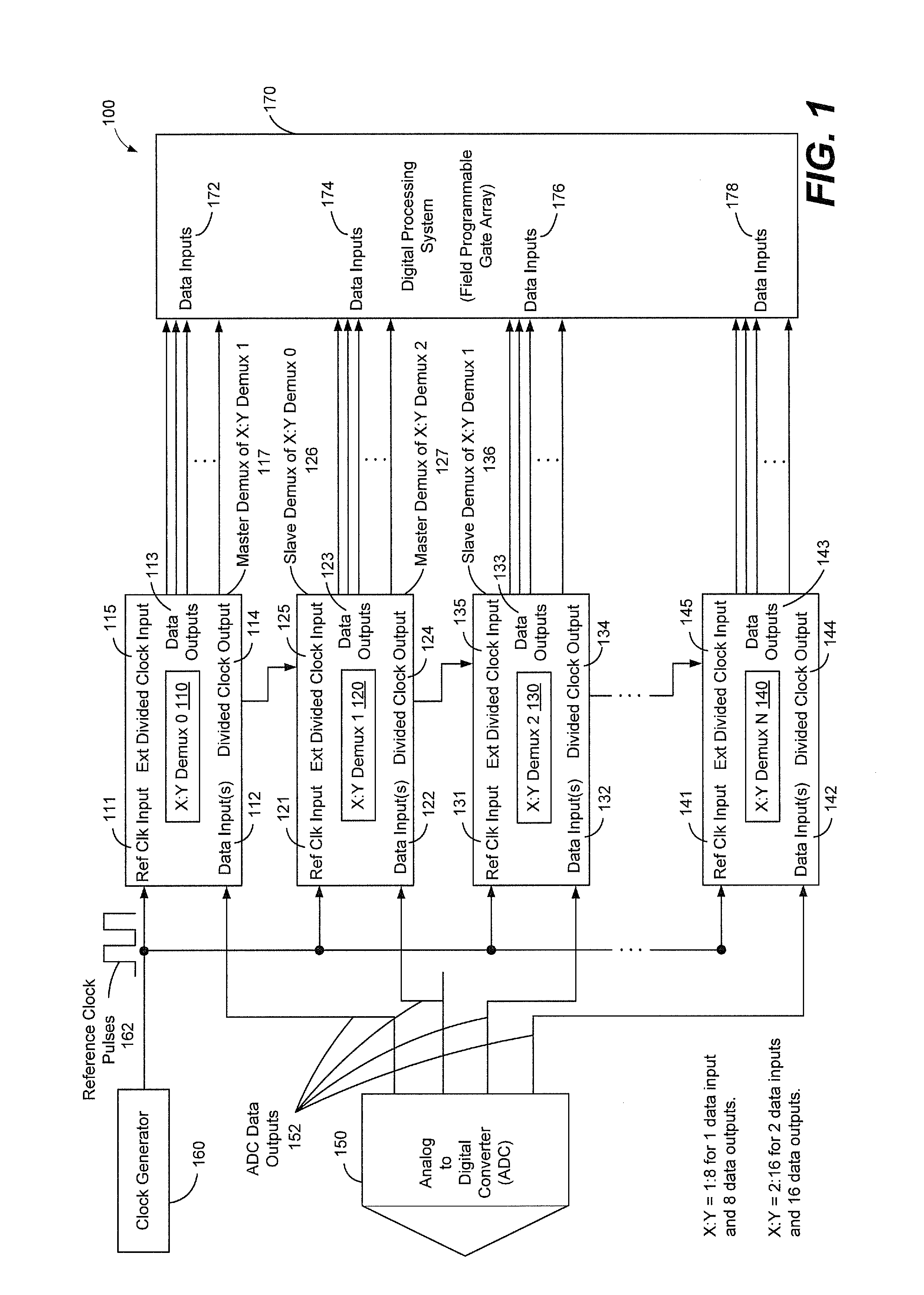
FIG. 1 is a schematic diagram of a circuit 100 including a demultiplexer that utilizes a...


PUM


Abstract

Circuits, demultiplexers, and methods are disclosed. A circuit includes a reference clock input to receive clock pulses at a reference clock speed. An internal divided clock input receives a divided clock signal from a clock divider that is driven by the clock pulses. The clock divider generates the divided clock signal at a second clock speed that is a fraction of the reference clock speed. An external divided clock input receives an external divided clock signal. The external divided clock signal is driven by the clock pulses and operates at the second clock speed. A clock transition synchronization circuit suppresses application of one or more of the clock pulses to the clock divider when the divided clock signal transitions between clock states out of synchronization with the external divided clock signal.

Description

FIELD OF THE DISCLOSUREThe present disclosure is generally related to synchronizing a transition between clock states of a divided clock signal in each of plurality of electronic devices.BACKGROUNDThe continued development and proliferation of digital technology results in large quantities of digital data being generated, transmitted, collected, processed, and stored. For example, in processing a large quantity of information, such as a data stream from a satellite, conversion of raw data by a fast analog-to-digital converter may generate a large stream of digital data. In order to accommodate the large stream of digital data, the stream may be deserialized into multiple separate streams of data that can be stored or processed by available digital devices.One way of deserializing a large digital data stream is to demultiplex the data stream with the demultiplexed outputs routed to separate digital devices or to separate inputs of a digital system. However, demultiplexing the digital...

Claims


Application Information

Patent Timeline
Patent Type & Authority Patents(United States)
IPC IPC(8): H03L7/00
CPCH03K5/135H03K5/15026H04J3/047H04J3/0685
Inventor SHRINGARPURE, RAHULBARINGER, CYNTHIA D.
Owner THE BOEING CO
Why Eureka
Try Eureka