
Device and method for detecting disc defect

a technology of disc track and defect, applied in the field of devices and methods for detecting disc defects, can solve problems such as optical pickup head b>100/b> to have focusing failure or slip track, and defects are readily formed on the surface of optical discs

Inactive Publication Date: 2009-05-28
SUNPLUS TECH CO LTD
View PDF9 Cites 16 Cited by
  • Summary
  • Abstract
  • Description
  • Claims
  • Application Information

AI Technical Summary

Benefits of technology

[0022]The present invention provides a defect-detecting circuit for detecting defects on a disc track by using two threshold values (slice signals) to determine the typical defect and the bright defect, thereby precisely controlling the timing of the defect signal.
[0023]The present invention provides a defect-detecting circuit having reduced layout space of the integrated chip.

Problems solved by technology

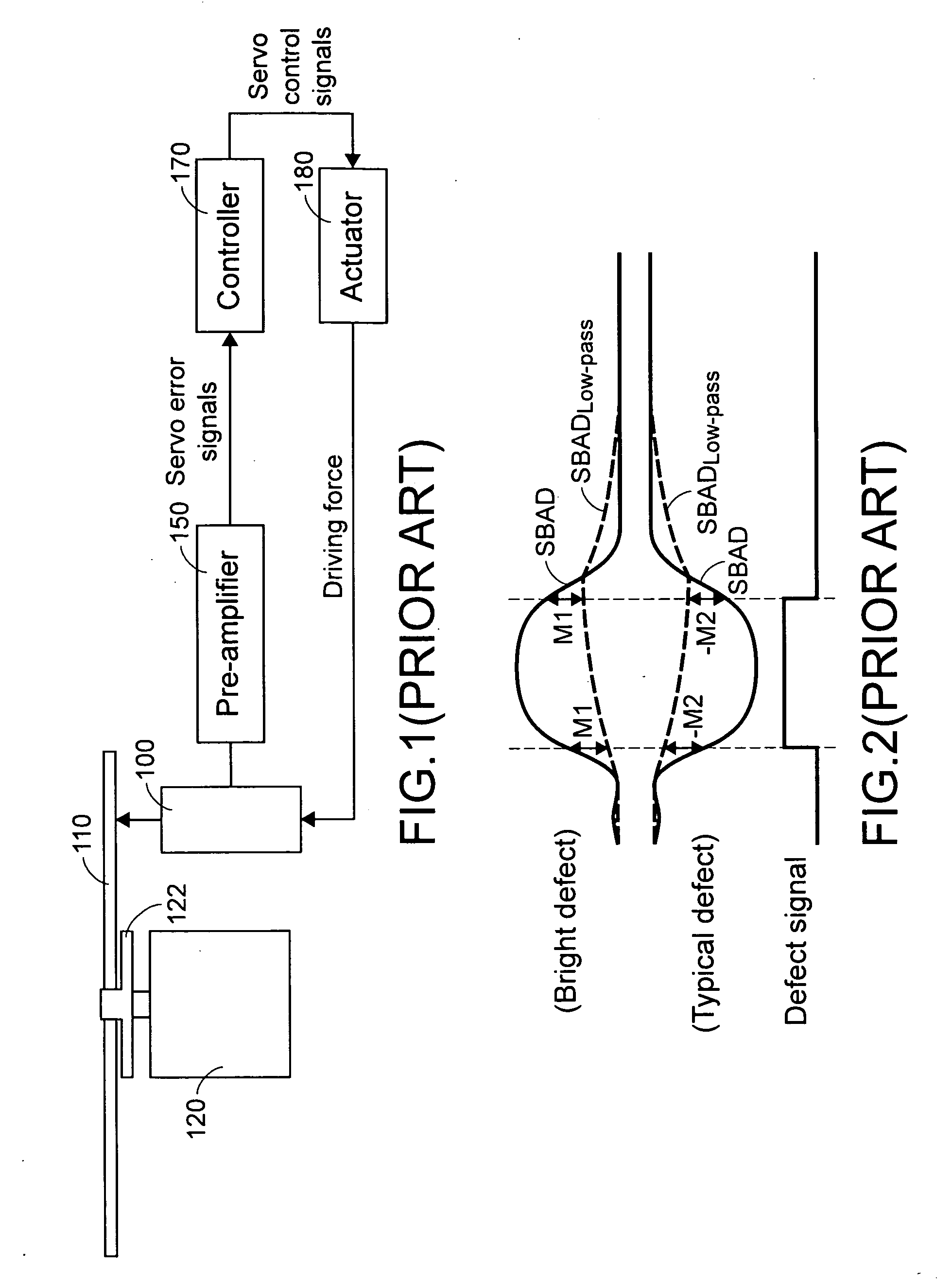
As known, due to production failure or scratch, some defects are readily formed on the surface of the optical disc 110.
The fluctuation of the servo error signals would further result in the unexpected servo control signals by the controller 170 and thus the actuator 180 may generate improper driving forces.
Under this circumstance, the servo control system of the optical disc drive is unstable, which may cause the optical pickup head 100 to have focusing fail or slip track.
Eventually, these defects could result in reading or writing errors.
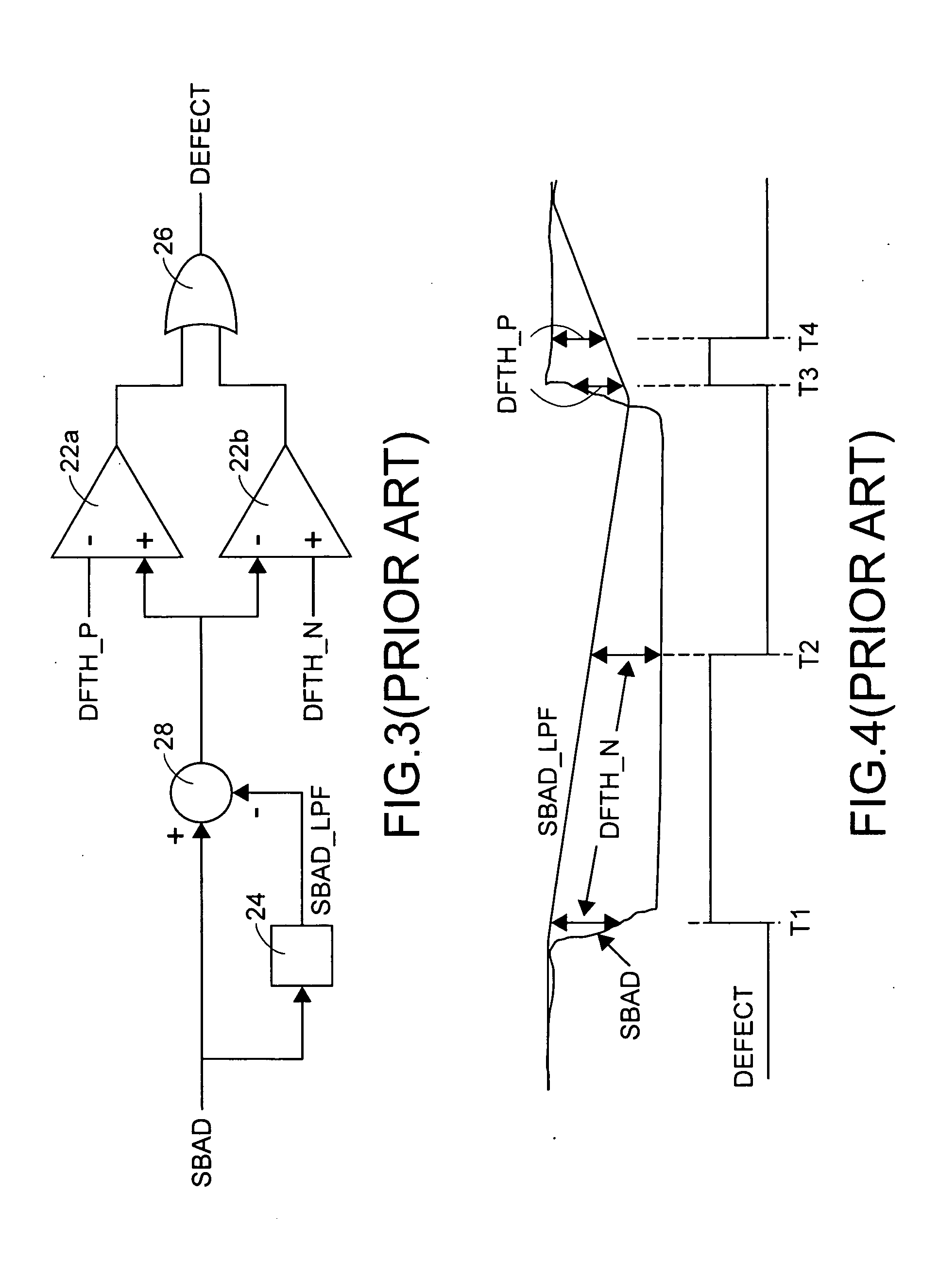
However, the above defect-detecting circuit usually generates inaccurate defect signals during the optical pickup head moves along the track having the long defect area.
As previously described, an erroneous defect signal is generated if a long defect is present.
Moreover, it is difficult to precisely control the timing of the defect signal changing from the first level to the second level.
That is, it is not flexible to adjust the time spots T5 and T6.
Since either the first threshold value TH1 or the second threshold value TH2 is used to determine one kind of defect (the typical defect or the bright defect), it is also difficult to precisely control the timing of the defect signal changing from the first level to the second level.

Method used


Image

  • Device and method for detecting disc defect
  • Device and method for detecting disc defect
  • Device and method for detecting disc defect

Examples


Embodiment Construction

[0038]The present invention will now be described more specifically with reference to the following embodiments. It is to be noted that the following descriptions of preferred embodiments of this invention are presented herein for purpose of illustration and description only. It is not intended to be exhaustive or to be limited to the precise form disclosed. The schematic drawings, not to scale, are employed to illustrate the specific features of the present invention.

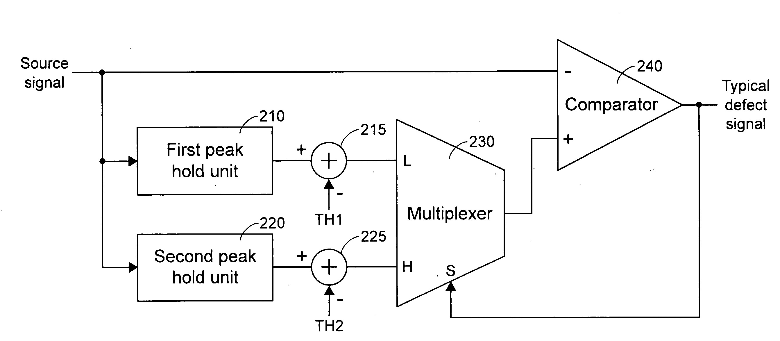
[0039]Referring to FIG. 8, a typical defect-detecting circuit for detecting typical defects according to a first preferred embodiment of the present invention is illustrated. The typical defect-detecting circuit of FIG. 8 principally includes a first peak hold unit 210, a first subtractor 215, a second peak hold unit 220, a second subtractor 225, a multiplexer 230 and a comparator 240. A source signal, e.g. a sub-beam added signal SBAD, a RF envelope signal or a RF top envelope signal, is inputted into a negative input...


PUM


Abstract

A method for detecting a typical defect area on a disc track includes the following steps. Firstly, a source signal is provided. Then, first and second signals are generated according to the source signal. The first and second signals are held at the peak level of the source signal and respectively decreased at first and second drop rates. Then, first and second threshold values are subtracted from the first and second signals to generate first and second slice signals, respectively. Afterwards, the source signal is compared with either the first slice signal or the second slice signal. When the first slice signal is larger than the source signal, a typical defect signal is changed from a first level to a second level. Whereas, the typical defect signal is changed from the second level to the first level when the second slice signal is smaller than the source signal.

Description

FIELD OF THE INVENTION[0001]The present invention relates to a device and a method for detecting a defect on a disc track, and more particularly to a defect-detecting device and a defect-detecting method for used in an optical disc drive.BACKGROUND OF THE INVENTION[0002]Referring to FIG. 1, a conventional servo control system of an optical disc drive is shown. An optical disc 110 having a center hole is placed on a turn table 122. The turn table 122 is driven to rotate by a spindle motor 120 such that the optical disc 110 is rotated with the turn table 122. An actuator 180 outputs a driving force for an optical pickup head (PUH) 100 of the optical disc drive in a tracking (radial) direction or a focusing direction.[0003]When an electronic signal is generated in response to the optical signal reflected from the optical disc 110 and received by the optical pickup head 100, a pre-amplifier 150 process the electronic signal into a series of servo error signals. The servo error signals i...

Claims


Application Information

Patent Timeline
IPC IPC(8): G11B20/18
CPCG11B2220/2537G11B20/1816
Inventor WANG, SIH-KAI
Owner SUNPLUS TECH CO LTD
Learn More