
Volume rendering apparatus and method

a volume rendering and volume technology, applied in the field of volume rendering, can solve the problems of complex motions that present particular challenges in rendering, the rendered image of a 4d) ct scan can be indistinct and of only limited use to the clinician, and the current state of the art ct scanner is not able to record a full cycle of the heart in one tak

Active Publication Date: 2009-05-28
TOSHIBA MEDICAL VISUALIZATION SYST EURO
View PDF4 Cites 25 Cited by
  • Summary
  • Abstract
  • Description
  • Claims
  • Application Information

AI Technical Summary

Benefits of technology

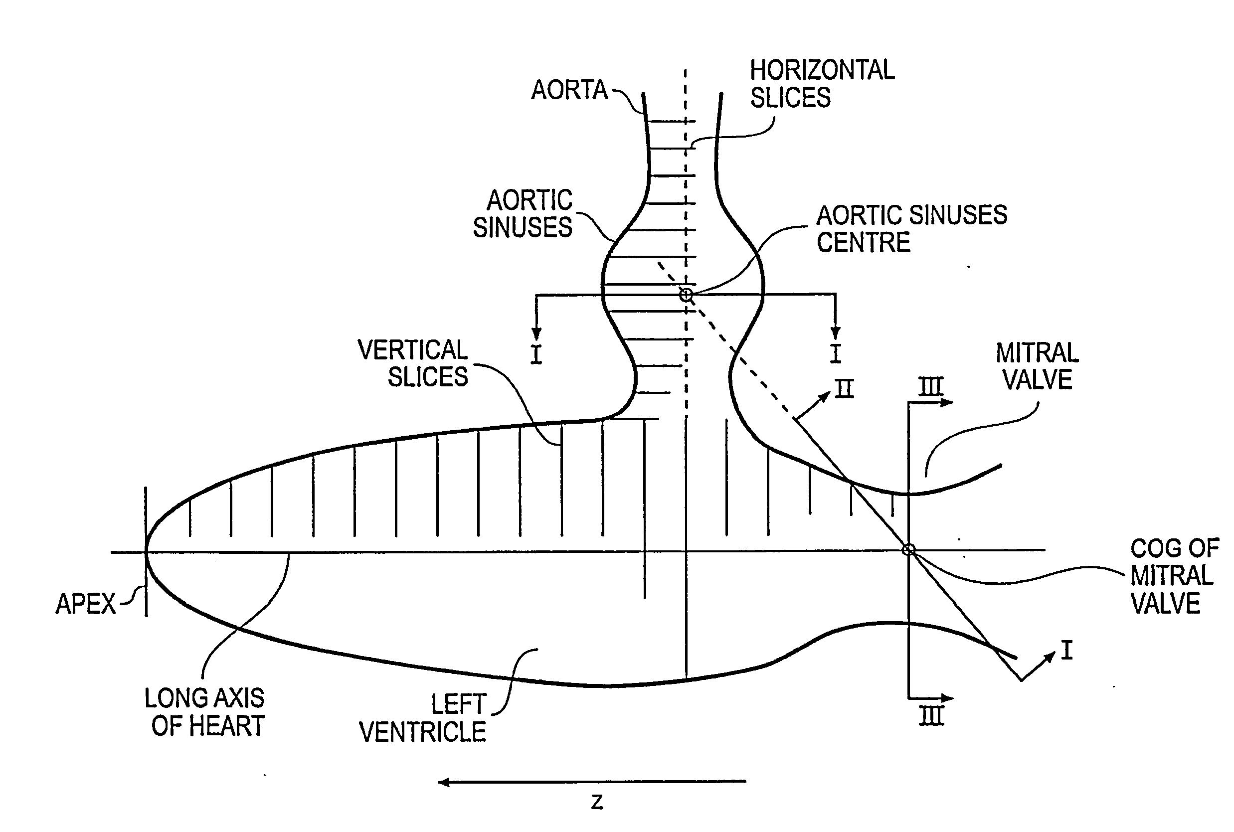
"The invention provides a computer-implemented method for volume rendering a sequence of frames over time of volume data depicting a heart. The method compensates for both translational motion and tilting effects, providing a stable image of a heart feature of interest. The method allows a user to view the feature of interest in a stable anatomical environment, free from distortions caused by the laboratory frame coordinate system or the patient's body. The method can be used for comparing different patients or for monitoring the condition of a heart over time. The invention also provides a computer-implemented method for automatically determining the view plane and orientation of the heart feature of interest."

Problems solved by technology

Current state of the art CT scanners are not able to record a full cycle of the heart in one take.
Specifically, while the heart is undoubtedly one of the most important organs to visualize in 4D so that its complex motions can be studied by a clinician, these complex motions present particular challenges for the rendering.
A rendered image of a 4D) CT scan can thus be indistinct and of only limited use to a clinician.
It appears from our searching that there is still a general lack of available methods and associated apparatus to allow high quality volume rendering in 4D of the heart, and in particular heart valves.

Method used


Image

  • Volume rendering apparatus and method
  • Volume rendering apparatus and method
  • Volume rendering apparatus and method

Examples


Embodiment Construction

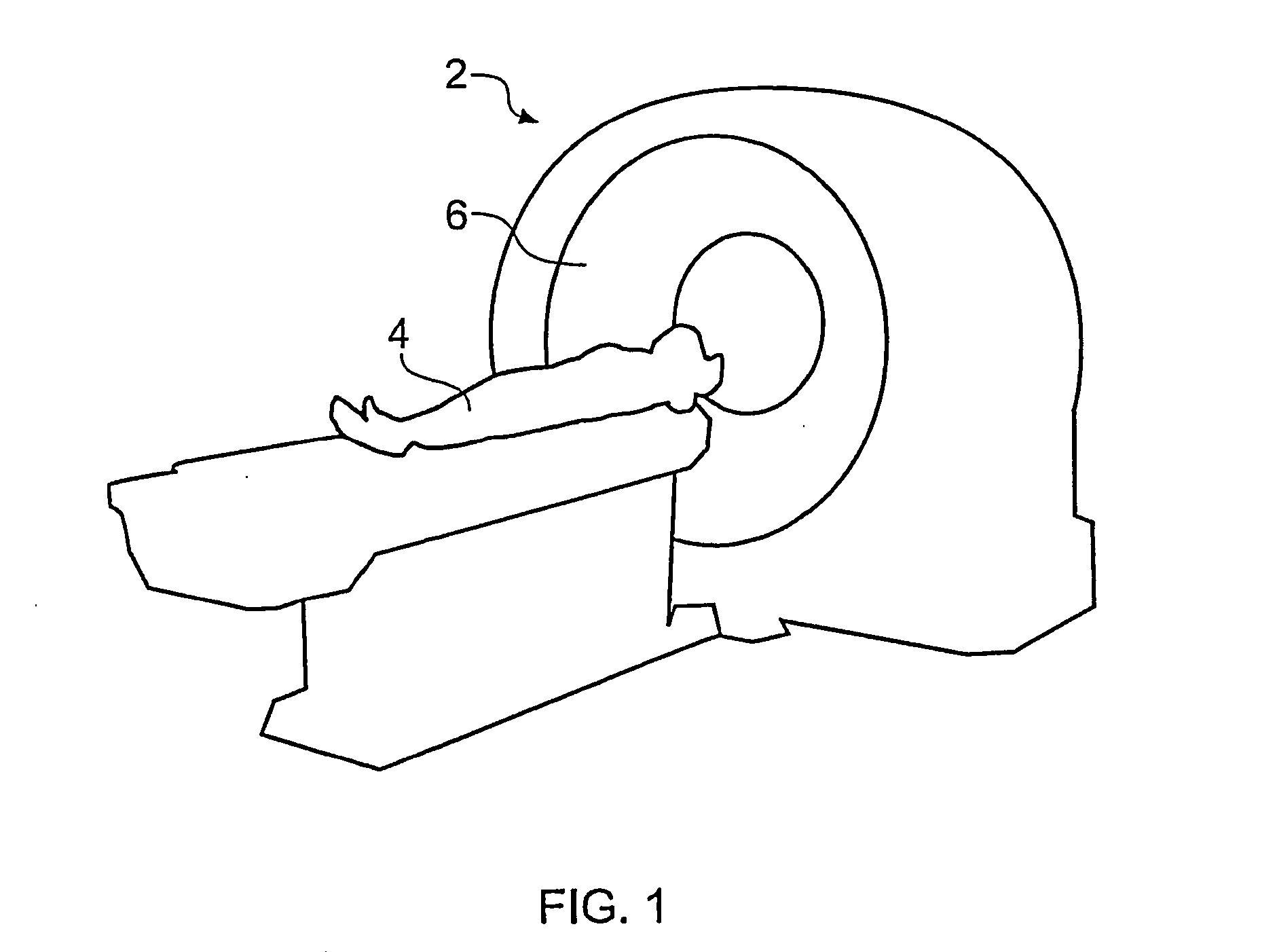
[0045]FIG. 1 is a schematic perspective view of a generic scanner 2, most especially a CT scanner, for obtaining a 3D scan of a region of a patient 4. An anatomical feature of interest (in this case the heart) is placed within a circular opening 6 of the scanner 2 and a series of image slices through the patient is taken. Raw image data are derived from the scanner and could comprise a collection of one thousand 2D 512×512 data subsets, for example. These data subsets, each representing a slice of the region of the patient being studied, are combined to produce volume data. The volume data comprise a collection of voxels each of which corresponds to a pixel in one of the slices. Thus the volume data are a 3D representation of the feature imaged and various user-selected 2D projections (output images) of the 3D representation can be displayed (typically on a computer monitor).

[0046]Different imaging modalities (e g. CT, MR, PET, ultrasound) typically provide different image resolutio...


PUM


Abstract

Volume rendering of images of four dimensional (4D) heart image data, in particular cardiac CT data by slab multiplanar reformatting (MPR), is improved by providing an automated method and apparatus for determining and locking onto anatomically relevant viewing parameters. In particular the view plane, view axis and view orientation are changed from frame to frame in the movie so they remain fixed to an anatomical feature of interest, thereby providing a stable movie of the heart feature of interest. Provision of a dynamic view plane compensates not only for translational motion of the heart feature of interest, but also for its tilting and twisting. Tilting effects are highly significant when viewing heart valves, since the valve plane exhibits varying angles of tilt through the heart phases as a result of the generally tubular arteries and veins exhibiting a bending motion.

Description

BACKGROUND OF THE INVENTION[0001]The invention relates to volume rendering, in particular to multi-planar reformatting (MPR) using a computer system that includes a graphics processing unit (GPU).[0002]Volume rendering is the standard visualization method for viewing two-dimensional (2D) representations of three-dimensional (3D) data sets and is widely used in medical imaging. MPR volume rendering is a standard rendering method for processing 3D data sets collected by medical imaging equipment, such as computer-assisted tomography (CT) scanners, magnetic resonance (MR) scanners, ultrasound scanners and positron-emission-tomography (PET) systems. These 3D data sets are sometimes referred to as volume data. General background on volume rendering can be found in the text book Lichtenbelt, B., Crane, R. and Naqvi, S., “Introduction to Volume Rendering”, Hewlett-Packard Company, Prentice-Hall PTR, New Jersey, 1998 [1].[0003]Medical image data sets are generally large. Sizes of between 0....

Claims


Application Information

Patent Timeline
Patent Type & Authority Applications(United States)
IPC IPC(8): G06K9/00G06T15/08
CPCG06T15/08G06T2219/008G06T2210/41G06T19/00
Inventor ROBERTS, COLINMELLER, SEBASTIAN
Owner TOSHIBA MEDICAL VISUALIZATION SYST EURO
Learn More