Direct carbon fuel cell

a fuel cell and carbon technology, applied in the field of fuel cells, can solve problems such as poor yield

Inactive Publication Date: 2009-05-28
GAS TECH INST
View PDF4 Cites 7 Cited by
  • Summary
  • Abstract
  • Description
  • Claims
  • Application Information

AI Technical Summary

Benefits of technology

[0012]It will be appreciated by those skilled in the art that the operation of the direct carbon fuel cell of this invention will result in the generation of excess carbonate which must be removed to avoid the performance problems of conventional direct carbon fuel cells. To enable removal of the excess carbonate, in accordance with one embodiment of this invention, the porous electrolyte matrix extends beyond the periphery of the metal flanges and is connected with a wicking material which is suitable for adsorbing or draining the excess carbonate. In accordance with one embodiment of this invention, the wicking material is melt adsorbent by means of capillary ac

Problems solved by technology

However, because the molten carbonate fuel cell matrix and cathode performance depend on an optimal carbonate filling based upon their pore structures and carbon

Method used


Image

  • Direct carbon fuel cell
  • Direct carbon fuel cell
  • Direct carbon fuel cell

Examples


Embodiment Construction

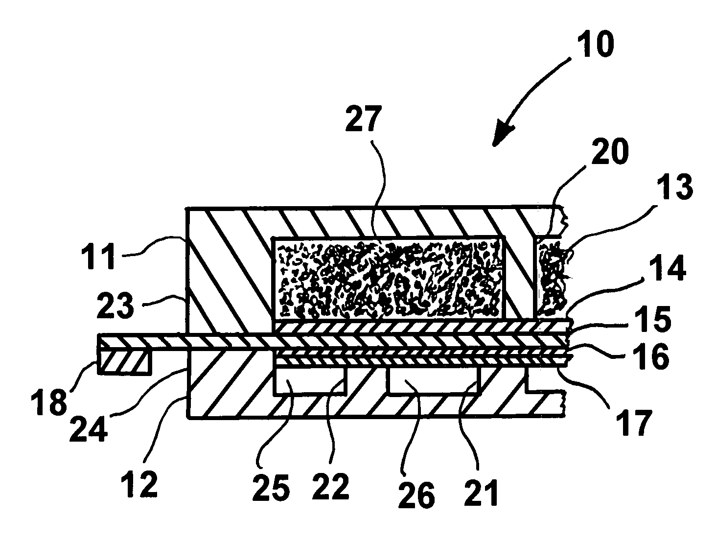
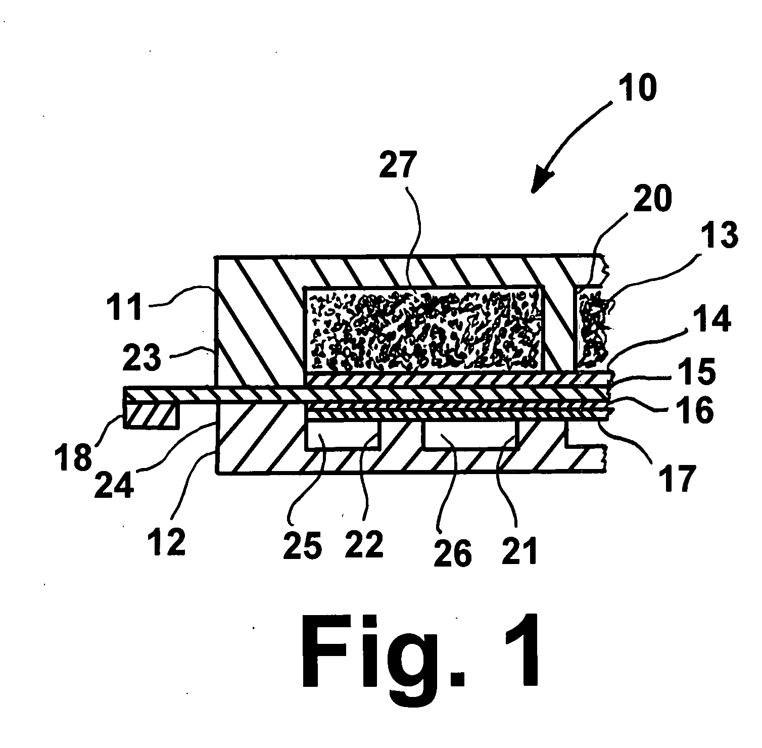
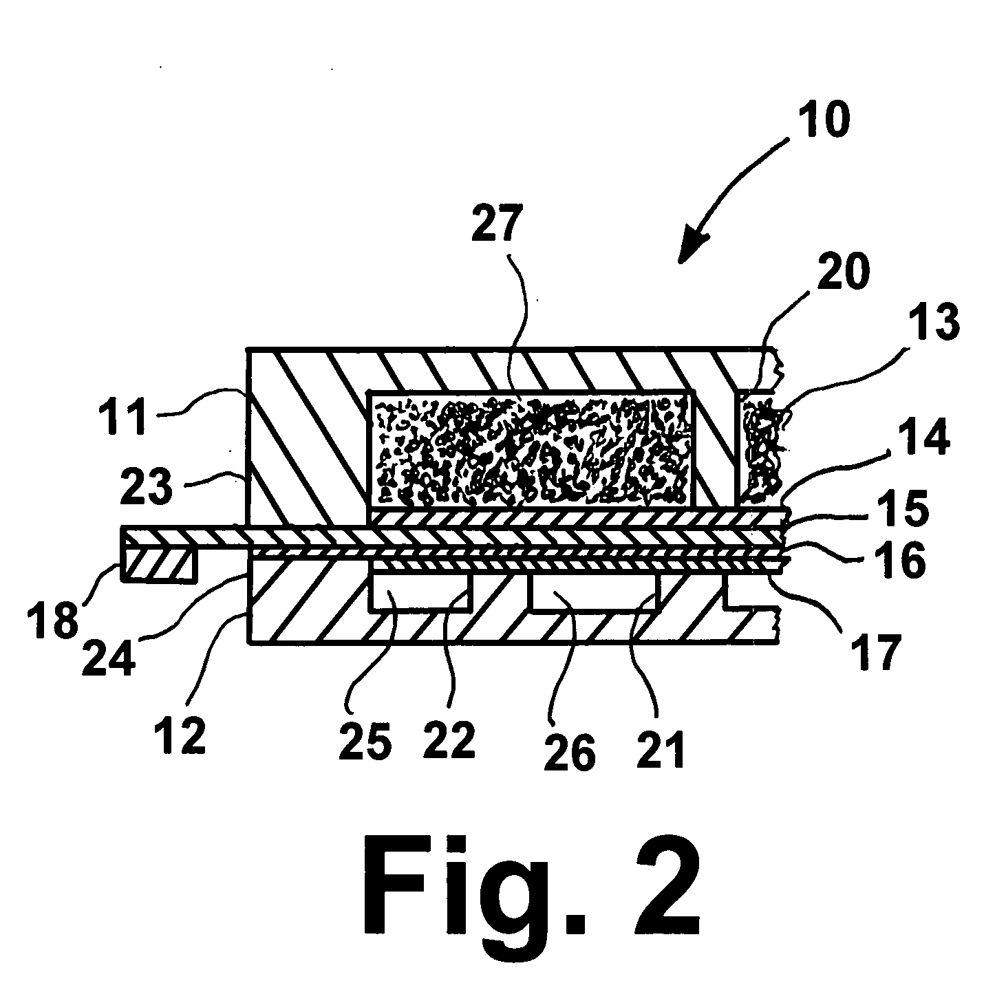
[0020]The direct carbon fuel cell 10 in accordance with one embodiment of this invention as shown in FIG. 1 comprises a fuel cell unit, i.e. anode electrode 13, cathode electrode 16, and electrolyte layer 15 between the anode and cathode electrodes, all of which are sandwiched between two metal flanges having a centralized active region and a peripheral sealing region, an anode flange 11 and a cathode flange 12, which house the reactants in the electrodes. The metal flanges may be comprised of suitable materials providing desired physical strength and reactant separation. For example, the metal flanges may be fabricated from ferrous alloys, such as type 300 series stainless steel. A portion of the electrolyte layer extends beyond the periphery of the metal flanges.

[0021]The peripheral sealing region of each metal flange comprises a raised peripheral wet seal structure 23, 24 which extends to contact the electrolyte layer, forming a peripheral wet seal with the electrolyte layer 15 a...


PUM


Abstract

A direct carbon fuel cell having an anode electrode of carbon particles pre-wetted with carbonate, a cathode electrode, and an electrolyte layer disposed between the anode electrode and the cathode electrode and containing a molten carbonate. The fuel cell includes a wicking feature whereby excess carbonate produced during the operation of the fuel cell is removed. The use of carbonate pre-wetted carbon particles as the anode provides a network of empty voids, facilitating the removal of CO2 gas from the cell, thereby enhancing fuel cell performance.

Description

BACKGROUND OF THE INVENTION[0001]1l. Field of the Invention[0002]This invention relates to fuel cells and, in particular, to fuel cells which directly convert solid carbon fuels such as coal, petroleum coke, pyrolyzed biomass, and organic wastes into electricity. This invention further relates to fuel cells which utilize molten carbonate as an electrolyte.[0003]2. Discussion of Related Art[0004]Whereas a conventional fuel cell converts gaseous hydrogen-based fuels into electricity, a direct carbon fuel cell (DCFC) uses solid carbon fuel to electrochemically generate electricity. The reactions involved are:Anodic reaction: C+2CO3==3CO2+4e−Cathodic reaction: O2+2CO2+4e−=2CO3=Overall reaction: C+O2═CO2 [0005]Like any fuel cell, direct carbon fuel cells are not limited by the Carnot cycle efficiency. The direct conversion of carbon to electricity is governed by the free energy change of the reaction. The conversion efficiency is the ratio of the free energy of the reaction at the operat...

Claims


Application Information

Patent Timeline
IPC IPC(8): H01M8/02
CPCH01M4/8657H01M4/96H01M8/0234H01M8/0245Y02E60/526H01M8/14H01M8/142H01M2004/8684H01M2008/147H01M8/0247Y02E60/50
Inventor ONG, ESTELA T.KRIST, KEVINSISHTLA, CHAKRAVARTHY
Owner GAS TECH INST
Why Eureka
Try Eureka