Compressed gas system useful for producing light weight drilling fluids

a compressed gas and fluid technology, applied in the direction of positive displacement liquid engines, carburetor air, separation processes, etc., can solve the problems of drilling bit stuck, operator fatigue, and resumption of desired downhole pressure and flow, so as to reduce the energy requirements of compressors and boosters, respond quickly, and economic and efficient

Inactive Publication Date: 2009-06-04
TOTAL SEPARATION SOLUTIONS
View PDF60 Cites 6 Cited by
  • Summary
  • Abstract
  • Description
  • Claims
  • Application Information

AI Technical Summary

Benefits of technology

[0006]Our system provides practical solutions to the above described problems and desiderata. We are able to deliver a steady supply of air or other gas to the well head for introduction to the well during drilling while also being able economically and efficiently to respond to sudden changes in demand for volume, pressure, ...

Problems solved by technology

A particular problem with air drilling is the resumption of desired downhole pressure and flow when drilling is interrupted to make piping connections.
Inadequate circulation of drilling fluid around the drill bit for too long of an interval can also result in a stuck drill bit, among other difficulties well known in the art.
The industry has developed various techniques to ameliorate these problems, but they continue to plague the operators.
But, even apart from the problem of connection time, the demand for air is not always steady.
Another problem more or less endemic in air drilling is the occasional sudden shift in demand for air as the drill bit penetrates through strata presenting different pressures, even greatly reduced pressures such as may be presented by penetrating an unforeseen cavity in the earth formation.
Sudden demands for significantly higher pressures mean sudden demands for significantly higher air volume, since air is compressible.
An inability to deliver the appropr...

Method used


Image

  • Compressed gas system useful for producing light weight drilling fluids
  • Compressed gas system useful for producing light weight drilling fluids
  • Compressed gas system useful for producing light weight drilling fluids

Examples


Embodiment Construction

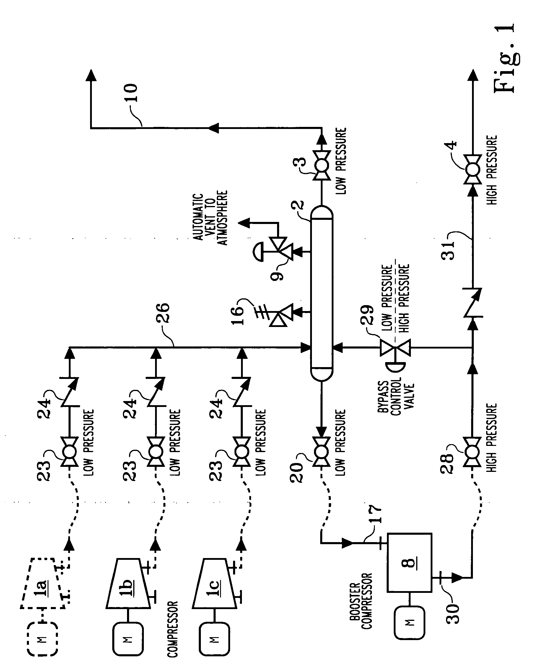
[0021]Referring now to FIG. 1, one or more—in this case, three—primary air compressors 1a, 1b, and 1c are connected in common through a manifold 26 to a volume bottle 2 capable of holding compressed air. Compressors 1a, 1b, and 1c are centrifugal compressors, but any compressor capable of performing the functions described herein is satisfactory in our invention. The compressed air passes through ball valves 23 and check valves 24 to the manifold 26 before entering volume bottle 2; depending on demand, the operator can use one, two or three compressors as needed. Volume bottle 2 acts to buffer changes in pressure, depending on downstream demands or conditions. Low pressure air from volume bottle 2 can flow through ball valve 3 and the low pressure end use line 10, or through ball valve 20 to the high pressure booster 8.

[0022]At least one of the compressors 1a, 1b, and 1c operates continuously, and is assisted by a booster compressor 8, here illustrated as a positive displacement com...


PUM

PropertyMeasurementUnit
Fractionaaaaaaaaaa
Pressureaaaaaaaaaa
Weightaaaaaaaaaa

Abstract

A compressor station having at least one primary compressor and a booster compressor is controlled to conserve energy and air, and to respond quickly to sudden changes in demand for air, by employing a volume bottle to buffer changes in air pressure and by recycling already compressed air from the intake to the output of the booster compressor. The system may be used in air drilling and to provide compressed air for generating low density drilling fluid on site by injecting microbubbles into a base drilling fluid. Two different methods of generating microbubbles are illustrated. The primary and booster compressors are kept in a state of readiness during drill pipe connection time, providing for a rapid resumption of pressure and air flow after connection is completed. The system can utilize gases other than air.

Description

RELATED APPLICATIONS[0001]This application claims the full benefit of Provisional Application 61 / 004,661 filed Nov. 29, 2007 and Provisional Application 61 / 062,932 filed Jan. 30, 2008, both of which are specifically incorporated herein in their entireties.TECHNICAL FIELD[0002]Light weight drilling fluids are provided while drilling a well, by introducing bubbles to the fluid. Utilizing primary compressors and a booster compressor, the system responds to interruptions and resumptions of air supply during drill pipe connections and other abrupt or significant changes in system demand, by allocating air (or other gas) into the drilling fluid or into a compressed gas storage and / or recycling system. The system is versatile in that it may deliver 100% air (gas) to the drill pipe, and may be used in contexts other than well drilling.BACKGROUND OF THE INVENTION[0003]In drilling wells for oil and gas, air drilling has been used successfully for many underbalanced and other drilling operatio...

Claims


Application Information

Patent Timeline
IPC IPC(8): B01F3/04F04B23/04C09K23/00
CPCB01F3/04446B01F3/0446B01F7/00833B01F5/0465B01F7/00816B01F5/0453B01F23/235B01F23/232B01F25/313311B01F25/3132B01F27/2724B01F27/2722
Inventor SMITH, RANDY J.HOBBS, PATRICK F.BELLINGER, CHARLES F.SMITH, KEVIN W.
Owner TOTAL SEPARATION SOLUTIONS
Why Eureka
Try Eureka