Solar charger

a solar charger and charger body technology, applied in the field of solar chargers, can solve the problems of inability to charge electronic devices through traditional chargers, inability to solve problems such as inability to charge solar charging devices of the prior arts, and inability to recharge solar energy devices, etc., to save manufacturing and processing costs, reduce unnecessary waste, and reduce time consumption. effect of fabrication

Inactive Publication Date: 2009-06-04
LEE VINCENT
View PDF4 Cites 14 Cited by
  • Summary
  • Abstract
  • Description
  • Claims
  • Application Information

AI Technical Summary

Benefits of technology

[0008]The disclosure of present invention permits the main body and the solar panel of a solar charger to be separately made as a respective modulized component, so as to save costs of manufacturing as well as processing and reduce time consumption during fabricating. Further, when one of the main body and the solar panel is broken or lost, replacement or supplement can be conducted upon the broken or lost component without discarding the entire solar charger so as to reduce unnecessary waste. Moreover, according to the present invention, the assembly, disassembly, and compacting between the main body and the solar panels are facile and rapid. Particularly, the two solar panels can be assembled at one of the edges of the main body for storage in the manner that the light collecting surfaces of the two solar panels face each other so as to protect the light collecting surfaces from being impacted or scraped. Consequently, the safety of the solar panels is ensured and the overall width of the solar charger can be substantially reduced so as to reduce required space and facilitate portability as well as storage. Furthermore, one or both of the solar panels can be assembled to the main body according to practical needs, so as to permit enhanced flexibility of assembly. Thereupon, the efficiency of power transformation and store can be freely controlled by the user. Additionally, the user can determine to charge the rechargeable battery with the solar panels or a normal AC or DC source so that the solar charger is prevented from lacking for an accessible power source.

Problems solved by technology

However, when power cut happens or when the user is in the outdoors where a power outlet is not accessible, it is impossible to charge the electronic device through the traditional charger.
Nevertheless, the solar charging devices of the prior arts still have problems to be remedied.
Thus, some of them are inevitably complicated and require relatively higher costs of manufacturing, processing and fabricating.

Method used


Image

  • Solar charger
  • Solar charger
  • Solar charger

Examples


Embodiment Construction

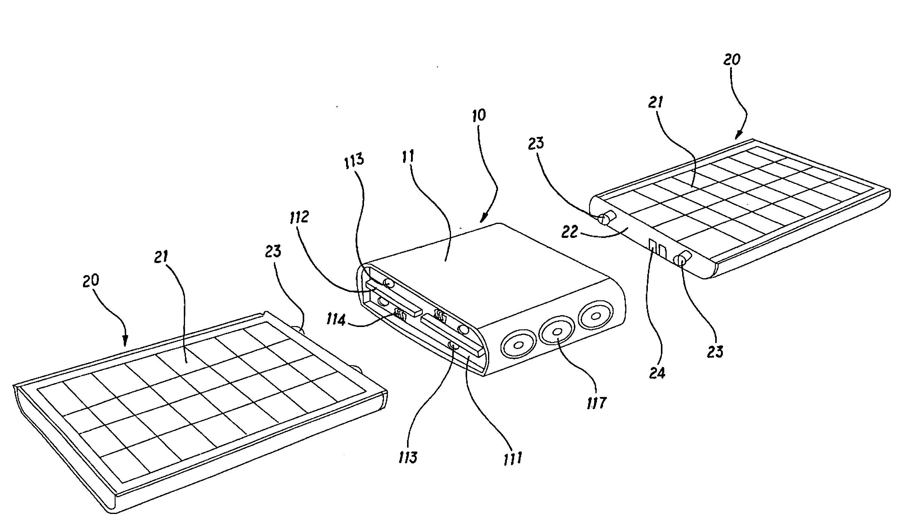
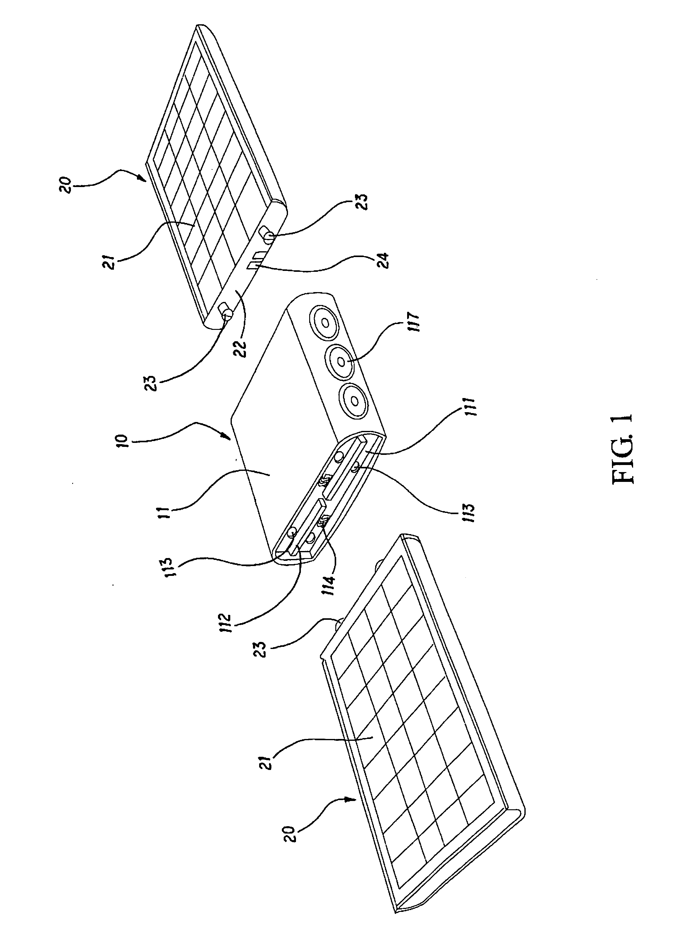
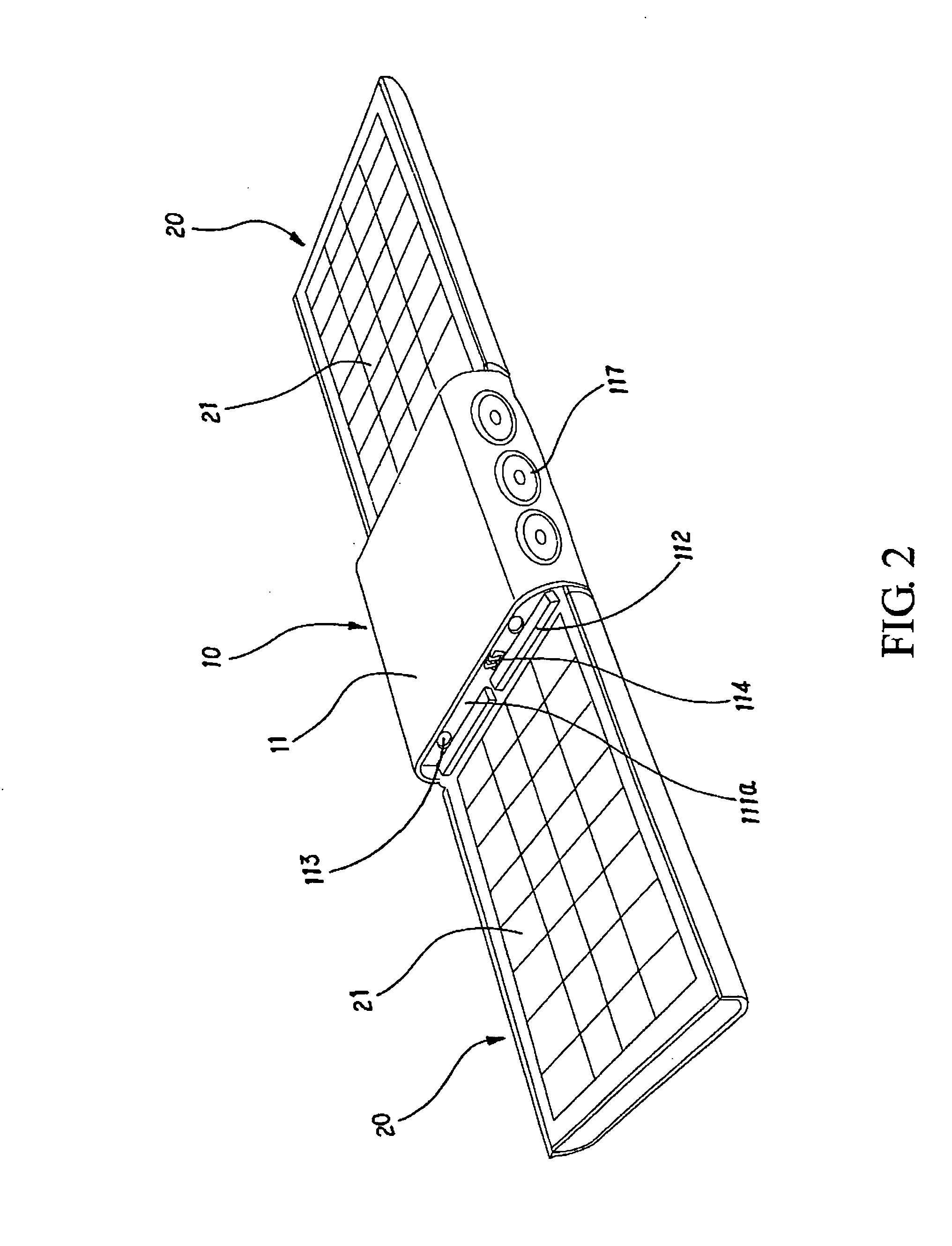
[0017]Please refer to FIGS. 1 and 2 for one preferred embodiment of the solar charger of the present invention. The solar charger comprises a main body 10 and two solar panels 20, which will be further explained in detail through the following description.

[0018]The main body 10, referring also to FIGS. 5, 6 and 7, comprises a approximately rectangular housing 11. Inside the housing 11, a rechargeable battery 12 and a circuit board (not shown) are provided. A charging unit 13 and a discharging unit 14 are arranged on the circuit board and are respectively connected to the rechargeable battery 12, as shown in FIG. 7, for preventing the rechargeable battery 12 from being over charged or over discharged. Further, each of two opposite edges of the housing 11 has a depressed portion 111, and two partitions 112 are transversely positioned in a middle part of the depressed portion 111 and distant from each other with a proper distance so that the depressed portion 111 is divided into a firs...


PUM


Abstract

A solar charger primarily comprises a main body and at least one solar panel wherein the main body and the solar panel are respectively an independent modulized component. In addition, one edge of the solar panel can be detachably attached to one adjacent edge of the main body. Since contacts are respectively provided on the adjacent edges of the solar panel and the main body, the two components are electrically connected when they are assembled together so as to store an electric power transformed from a light energy in a rechargeable battery in the main body for providing the electric power to charge electronic devices later. Thereupon, the present invention facilitates manufacturing as well as processing and reduces time consumption of fabricating.

Description

BACKGROUND OF THE INVENTION[0001]1. Technical Field[0002]The present invention relates to solar chargers and, more particularly, to a solar charger comprising one main body and at least one solar panel, which are respectively an independent modulized component, wherein the solar panel can be detachably attached to the main body.[0003]2. Description of Related Art[0004]There are many portable 3C electronic devices available on the market, such as PDA, ipod and DV. Users bringing these electronic devices out or during their travel usually bring extra batteries for preventing the electronic devices from running out of power. For those users don't have extra batteries, they may have to bring chargers instead. A traditional charger typically uses a wire connected with an AC / DC (alternating current / direct current) converter that further connected with an outlet of the grid to charge a battery of a mentioned electronic device. However, when power cut happens or when the user is in the outd...

Claims


Application Information

Patent Timeline
Patent Type & Authority Applications(United States)
IPC IPC(8): H02J7/00
CPCH02J7/355H02J7/35
Inventor LEE, VINCENT
Owner LEE VINCENT
Why Eureka
Try Eureka