
Compact camera optics

a compact, camera technology, applied in the direction of cameras, instruments, printers, etc., can solve the problems of blurred images captured by the array itself, psf of the resulting optical system may still vary from the ideal, etc., and achieve the effect of high-quality outpu

Active Publication Date: 2009-06-04
NANCHANG O FILM OPTICAL ELECTRONICS TECH CO LTD
View PDF11 Cites 20 Cited by
  • Summary
  • Abstract
  • Description
  • Claims
  • Application Information

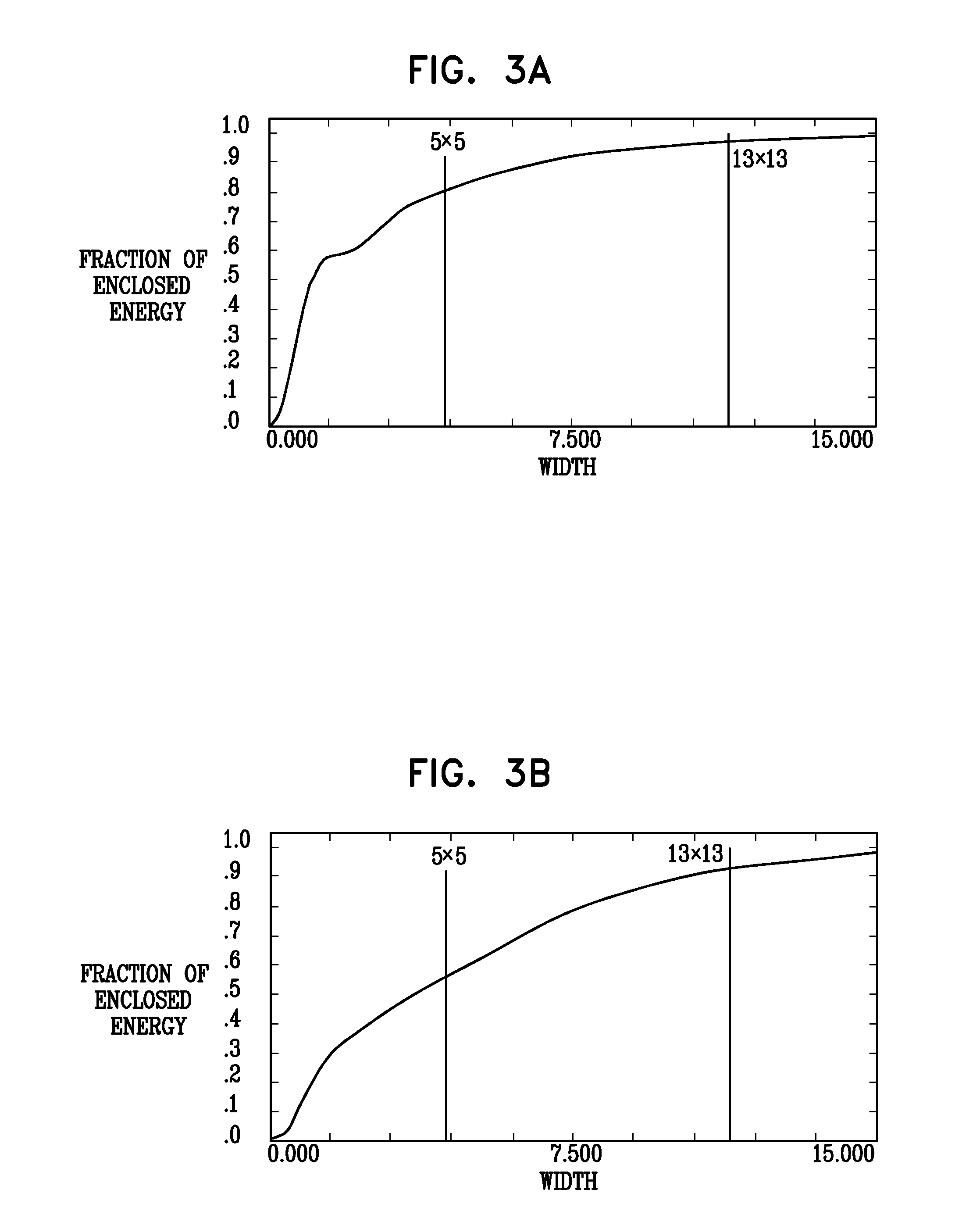
AI Technical Summary

Benefits of technology

[0009]Embodiments of the present invention that are described hereinbelow provide optical designs that can be used in conjunction with deconvolution filtering to provide high-quality output images.
[0011]In a disclosed embodiment, the second width is thirteen times the pitch, and the second threshold percentage is greater than the first threshold percentage by at least 10%. In one example, the first threshold percentage is 80%, and the second threshold percentage is 90%. Typically, the kernel of the digital filter is selected responsively to the PSF so that the output image has a reduced blur relative to the input image. Optionally, the digital filter has a first kernel for reducing the blur in the output image for a first field extending from a reference distance to infinity and a second kernel, different from the first kernel, for reducing the blur in the output image for a second field extending from a specified near distance to the reference distance.

Problems solved by technology

The PSF of the resulting optical system may still vary from the ideal due to focal variations and aberrations.
As a result, the images captured by the array itself are blurred.

Method used


Image

  • Compact camera optics
  • Compact camera optics
  • Compact camera optics

Examples


Embodiment Construction

Definitions

[0023]The following is a non-exhaustive list of technical terms that are used in the present patent application and in the claims. Although these terms are used herein in accordance with the plain meaning accorded the terms in the art, they are listed below for the convenience of the reader in understanding the following description and the claims.[0024]Pitch of a detector array, such as an image sensor, refers to the center-to-center distance between elements of the array. Each element corresponds to a pixel in the image output by the array.[0025]Cylindrical symmetry describes a structure, such as a simple or compound lens, which has an optical axis such that the structure is invariant under rotation about the optical axis for any and all angles of rotation.[0026]Point spread function (PSF) is the impulse response of an optical system in the spatial domain, i.e., the image formed by the system of a bright point object against a dark background.[0027]Extent of the PSF is ...


PUM


Abstract

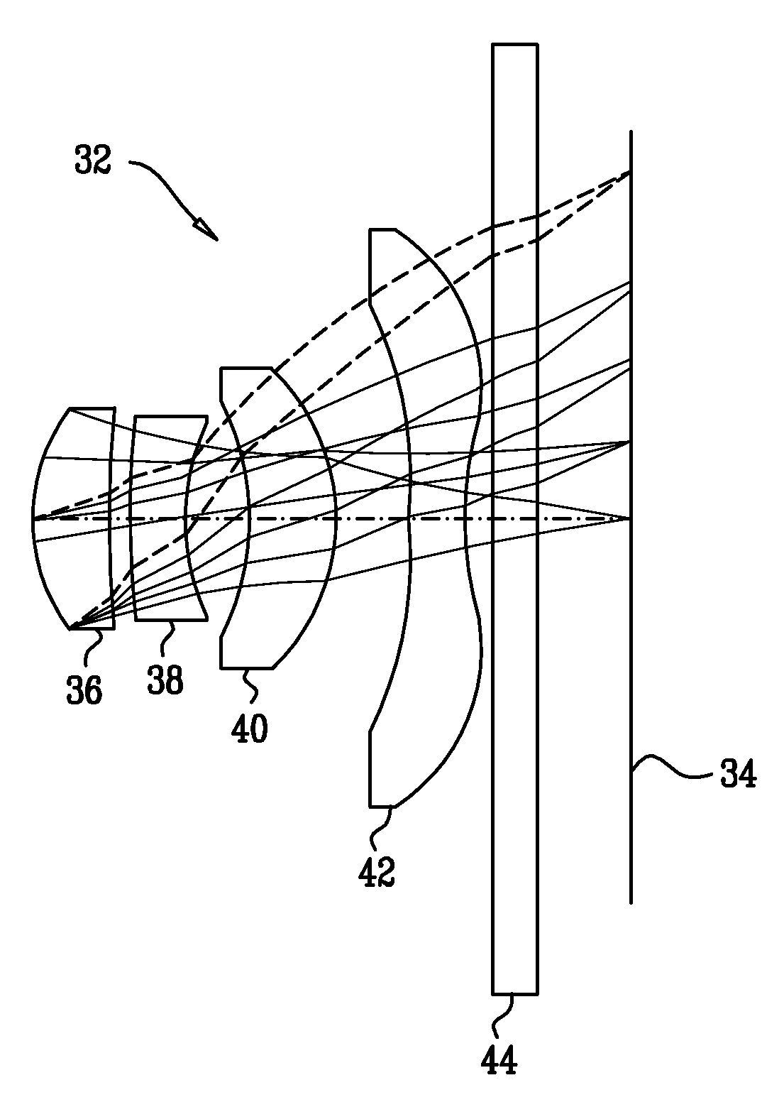
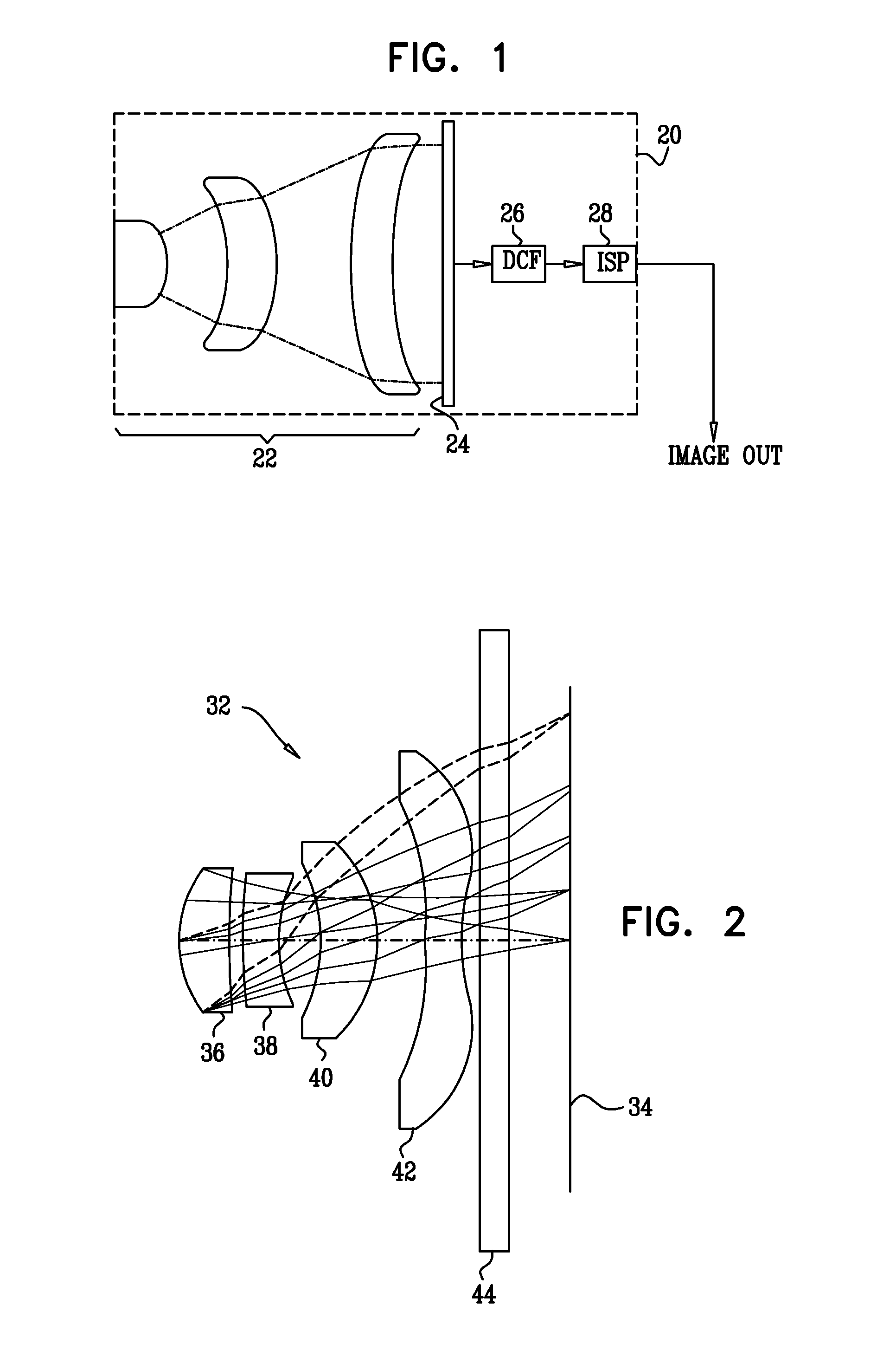
Imaging apparatus includes an image sensor, which is adapted to generate an input image in response to optical radiation that is incident thereon. A processing engine is configured to apply a digital filter to the input image so as to generate a filtered image, the digital filter having a kernel, which has a kernel width that is greater than five pixels. An optical assembly is arranged to focus the optical radiation onto the image sensor with a point spread function (PSF) such that no more than a first threshold percentage of energy emitted from a point object and focused by the optical assembly falls within a first region of the image sensor having a first width that is five times the pitch of the image sensor, while at least a second threshold percentage of the energy emitted from the point object and focused by the optical assembly falls within a second region, which contains the first region and has a second width corresponding to the kernel width.

Description

CROSS-REFERENCE TO RELATED APPLICATIONS[0001]This application claims the benefit of U.S. Provisional Patent Applications 60 / 992,164 and 61 / 005,428, both of which were filed Dec. 4, 2007, and are incorporated herein by reference.FIELD OF THE INVENTION[0002]The present invention relates generally to digital imaging, and specifically to optics for use in digital imaging cameras.BACKGROUND OF THE INVENTION[0003]The objective optics used in digital cameras are typically designed so as to minimize the optical point spread function (PSF) and maximize the modulation transfer function (MTF), subject to the limitations of size, cost, aperture size, and other factors imposed by the camera manufacturer. The PSF of the resulting optical system may still vary from the ideal due to focal variations and aberrations. A number of methods are known in the art for measuring and compensating for such PSF deviations by digital image processing. For example, U.S. Pat. No. 6,154,574, whose disclosure is in...

Claims


Application Information

Patent Timeline
IPC IPC(8): H04N5/232
CPCH04N5/23212G03B13/36H04N25/615
Inventor ATTAR, ZIVYADIN, YOAVALON, ALEX
Owner NANCHANG O FILM OPTICAL ELECTRONICS TECH CO LTD
Learn More