

Imaging lens system and capsule endoscope
a technology of endoscope and lens, which is applied in the field of imaging lens system, can solve the problems of difficult control of the position and direction of the insertion portion inside the body, more conspicuous distortion, and heavy load on the patient, and achieve the effect of improving distortion and being easy to swallow
- Summary
- Abstract
- Description
- Claims
- Application Information
AI Technical Summary
Benefits of technology
Problems solved by technology
Method used
Image

Examples
example 1
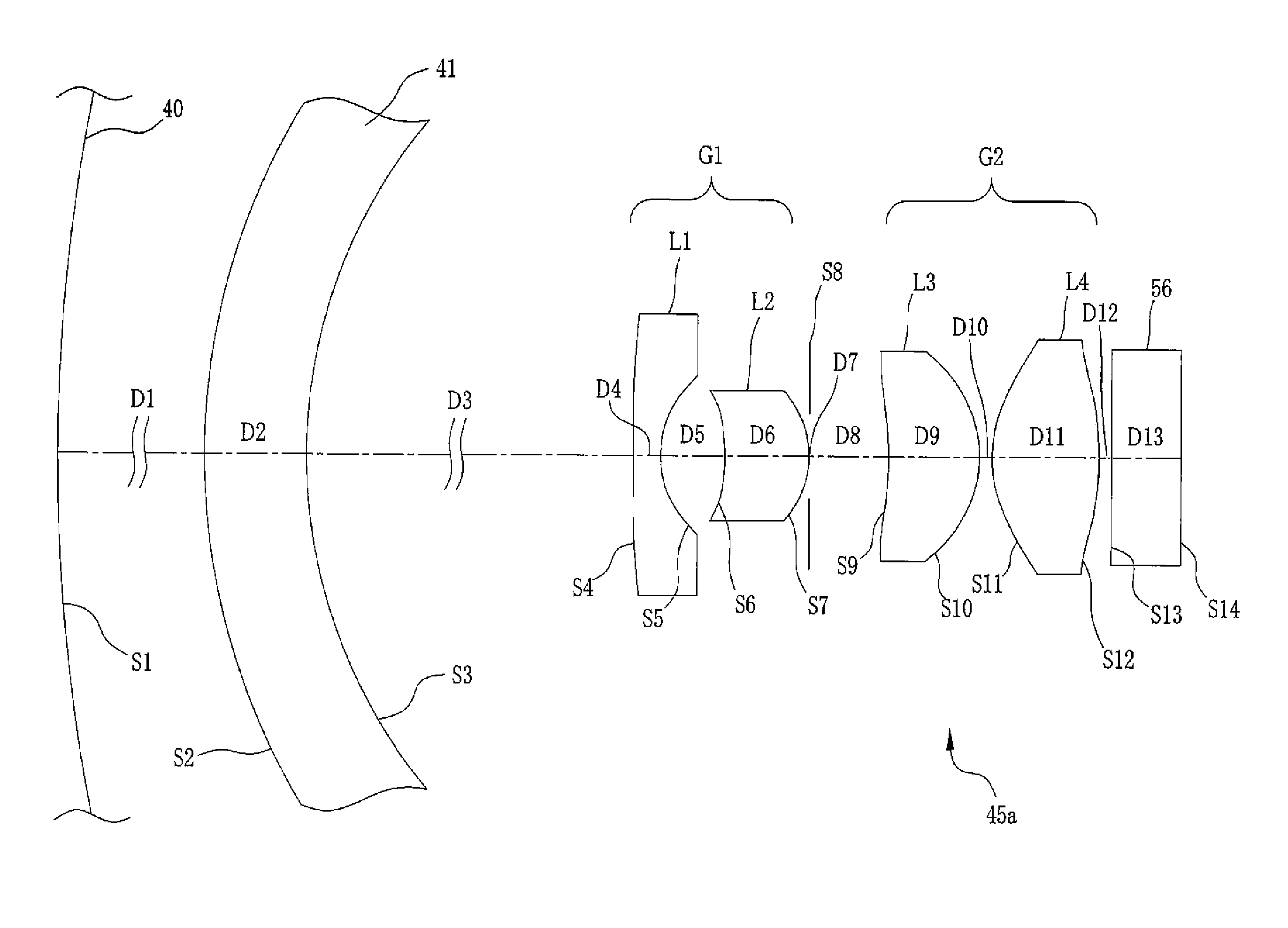
[0070]As shown in FIG. 6, an imaging lens system 45a includes, in order from the object side, a first lens L1 having a meniscus shape and having a convex surface directed to the object side, a second lens L2 having a meniscus shape and having a convex surface directed to the image side (imaging device side), an aperture diaphragm, a third lens L3 having a meniscus shape and a convex surface directed toward the image side, and a fourth lens L4 having a biconvex shape. A first lens group G1 of the imaging lens system 45a includes the first lens L1 and the second lens L2, which are disposed on the object side of the aperture diaphragm. The overall refractive power of the first lens group G1 is negative. A second lens group G2 of the imaging lens system 45a includes the third lens L3 and the fourth lens L4, which are disposed on the image side of the aperture diaphragm. The overall refractive power of the second lens group G2 is positive. The surface shapes and arrangement of these lens...
example 2
[0077]As shown in FIG. 9, a imaging lens system 45b includes, in order from the object side, a first lens L1 having a meniscus shape and having a convex surface directed toward the object side; an aperture diaphragm, a second lens L2 having a convex surface directed toward the image side, a third lens L3 having a biconvex shape, and a fourth lens L4 having a biconvex shape. A first lens group G1 of the imaging lens system 45b includes the first lens L1 deposed on the object side of the aperture diaphragm. The refractive power of the first lens group G1 is negative. A second lens group G2 of the imaging lens system 45b includes the second lens L2, the third lens L3, and the fourth lens L4, which are disposed on the image side of the aperture diaphragm. The overall refractive power of the second lens group G2 is positive. The surface shapes and arrangement of these lenses L1 to L4 are set in consideration of the front cover 41 and the cover glass 56 of the imaging device 46.
[0078]The ...
example 3
[0084]As shown in FIG. 12, a imaging lens system 45c includes, in order from the object side, a first lens L1 having a meniscus shape and having a convex surface directed toward the object side, an aperture diaphragm, a second lens L2 having a biconvex shape, a third lens L3 having a biconcave configuration, a fourth lens L4 having a biconvex shape, and a fifth lens L5 having a biconvex shape. A first lens group G1 of the imaging lens system 45c includes the first lens L1 deposed on the object side of the aperture diaphragm. The refractive power of the first lens group G1 is negative. A second lens group G2 of the imaging lens system 45c includes the second lens L2, the third lens L3, the fourth lens L4, and the fifth lens L5, which are disposed on the image side of the aperture diaphragm. The overall refractive power of the second lens group G2 is positive. Further, the opposed surfaces of the third lens L3 and the fourth lens L4 are cemented to form an achromatic lens LA. The surf...
PUM
 Abstract
Description
Claims
Application Information