
Flyline connecting device
a connecting device and flyline technology, applied in the direction of rod connection, coupling, manufacturing tools, etc., can solve the problems of not being most effectively or reliably connected to each other, difficult to re-insert the knot end of the flyline back into the link, and difficult to do without damaging the tensile bearing core, etc., to achieve the effect of reducing the inside diameter of the tubular lattice, wall section, and increasing tensile strength and toughness
- Summary
- Abstract
- Description
- Claims
- Application Information
AI Technical Summary
Benefits of technology
Problems solved by technology
Method used
Image

Examples
Embodiment Construction
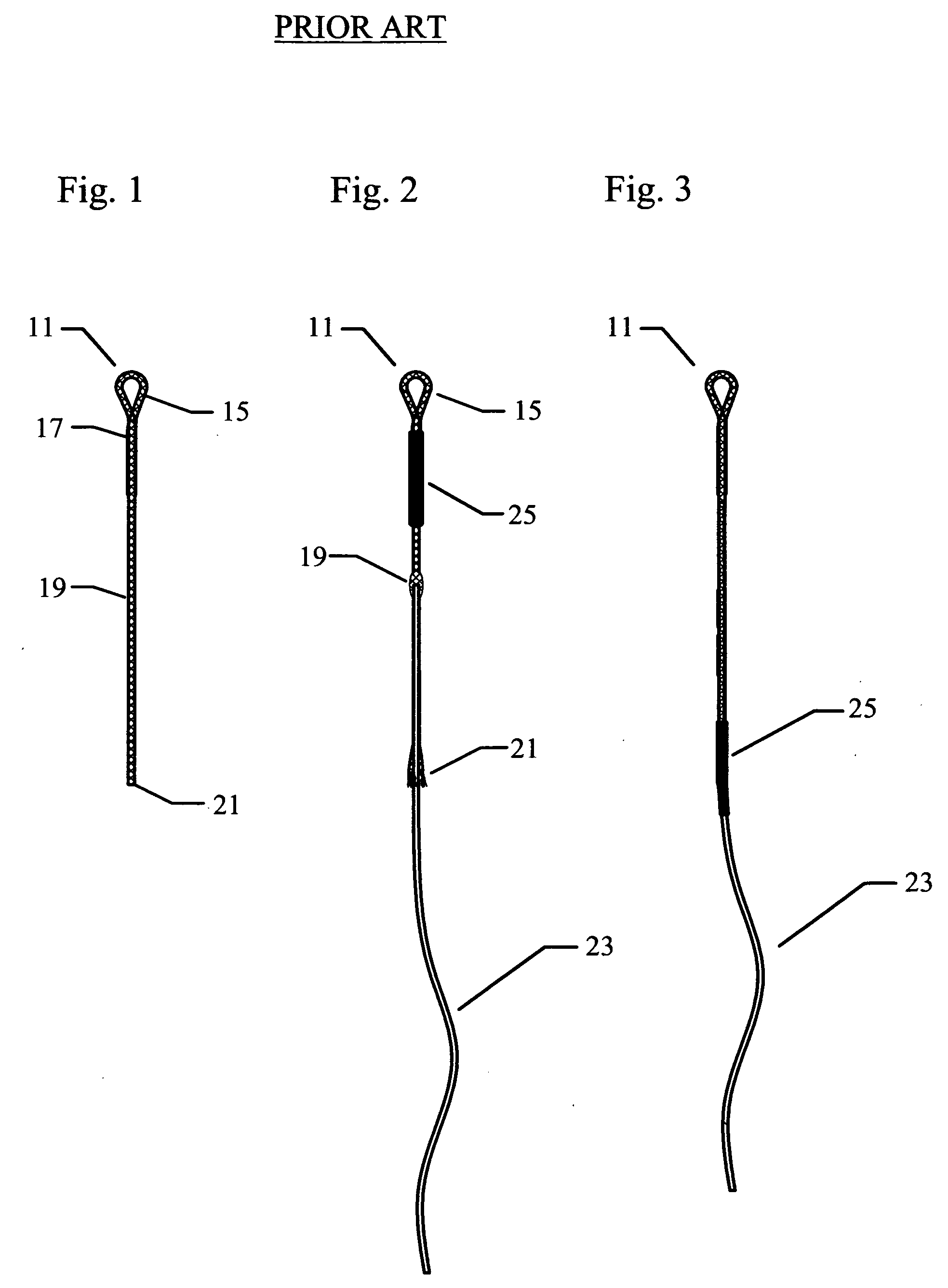
[0036]The prior art “braided loop” device 11 is shown in the FIGS. 1 through 3. The device 11 as shown in FIG. 1 is formed of a braided (nylon) tubular sleeve 19 with a hand formed loop at 15. The loop 15 is made by tucking the end of the braided sleeve back into a stretched region of the weave where it is secured by cementing approximately 1″ of overlapping length of the braided nylon as seen at17. The braided tubular sleeve 19 has an open tubular end to receive the fly line at 21. The FIG. 2 shows the fly line 23 being pushed into the expanded woven sleeve 19. The braided sleeve 19 opens up to receive the fly-line 21 as it is locally compressed. In order to get the fly line 23 fully inserted into the braided loop sleeve 19 it is necessary to tease the line further and further up the braided sleeve. This procedure is somewhat tedious as both the fly line and braided loop are prone to flexing. The braided loop device 11 stays in place on the fly-line 23 by a mechanism similar to how...
PUM
 Abstract
Description
Claims
Application Information