Electronic device and printed circuit board unit

a printed circuit board and electronic device technology, applied in the direction of memory architecture accessing/allocation, coupling device connection, instruments, etc., can solve the problems of cable pull-out or damage, complicated wired cable connection, flat cable and flexible printed circuit board, etc., to prevent cable pull-out and damage, reduce cost, and facilitate separation

Inactive Publication Date: 2009-06-04
FUJITSU LTD
View PDF9 Cites 4 Cited by
  • Summary
  • Abstract
  • Description
  • Claims
  • Application Information

AI Technical Summary

Benefits of technology

[0026]In recent years, flexible flat cables and flexible printed circuit boards have been widely used as small and light cables. However, there is a problem in that such flat cables are easily separated from a connector by twisting. According to the basic aspects, however, movement of the cable is specifically restrained by the through hole or recess in the printed circuit board. Hence, it is possible to reliably prevent cable pull-out and damage also with respect to a flexible flat cable or flexible printed circuit board is used.
[0027]As described above, according to the basic aspects of the electronic device and the printed circuit board unit, it is possible to reliably prevent cable pull-out and damage while suppressing cost increases.

Problems solved by technology

However, when attempting to fulfill both requirements of miniaturization and weigh reduction of a device and upsizing of a display screen, a liquid crystal panel, a hard disk, a cooling fan, a power source device, various circuit boards and the like tend to be tightly packed in the casing with little space between them.
As a result, cables for connecting them are complicatedly wired.
However, a flat cable and a flexible printed circuit board may be pulled out from their connectors or damaged when pulled or twisted at terminals.
Therefore, when an external force is unwittingly applied to a cable during maintenance or the like and the cable is pulled out or damaged, it may be difficult to find a location of the failure.
Moreover, the operation to reinstall the cable may be troublesome.
H5-46072 has a problem in that new jumper wires have to be fitted when the cable is reattached to the connector, and so the cost of reattachment is high.
A further problem is that sufficient space and a mechanism for fitting the jumper have to be provided inside the device, so that the device will increase in size.
H11-135188 also result in an increase in cost because a special connector having a hook is used so that a general-purpose connector may not be diverted.

Method used


Image

  • Electronic device and printed circuit board unit
  • Electronic device and printed circuit board unit
  • Electronic device and printed circuit board unit

Examples


first embodiment

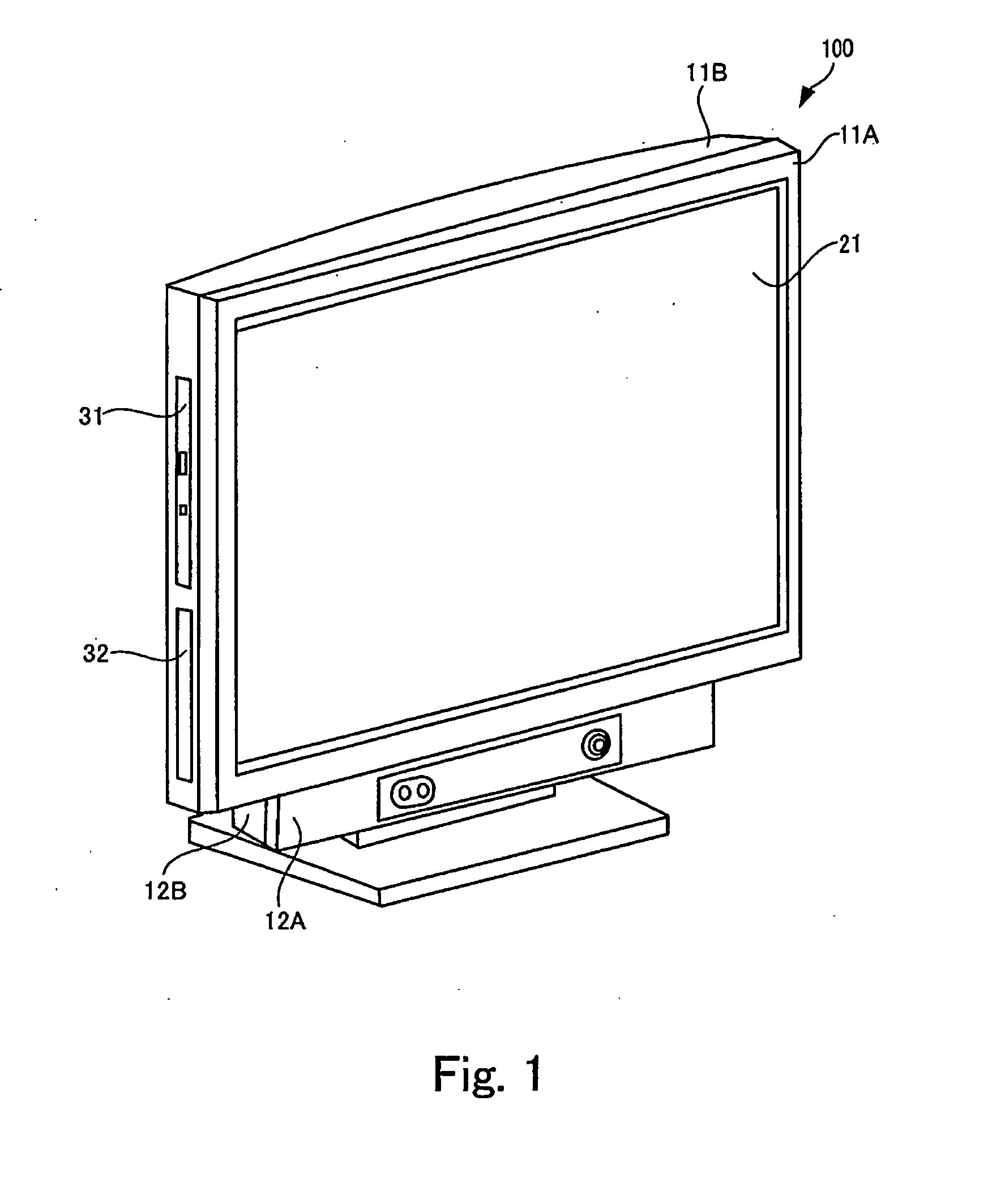
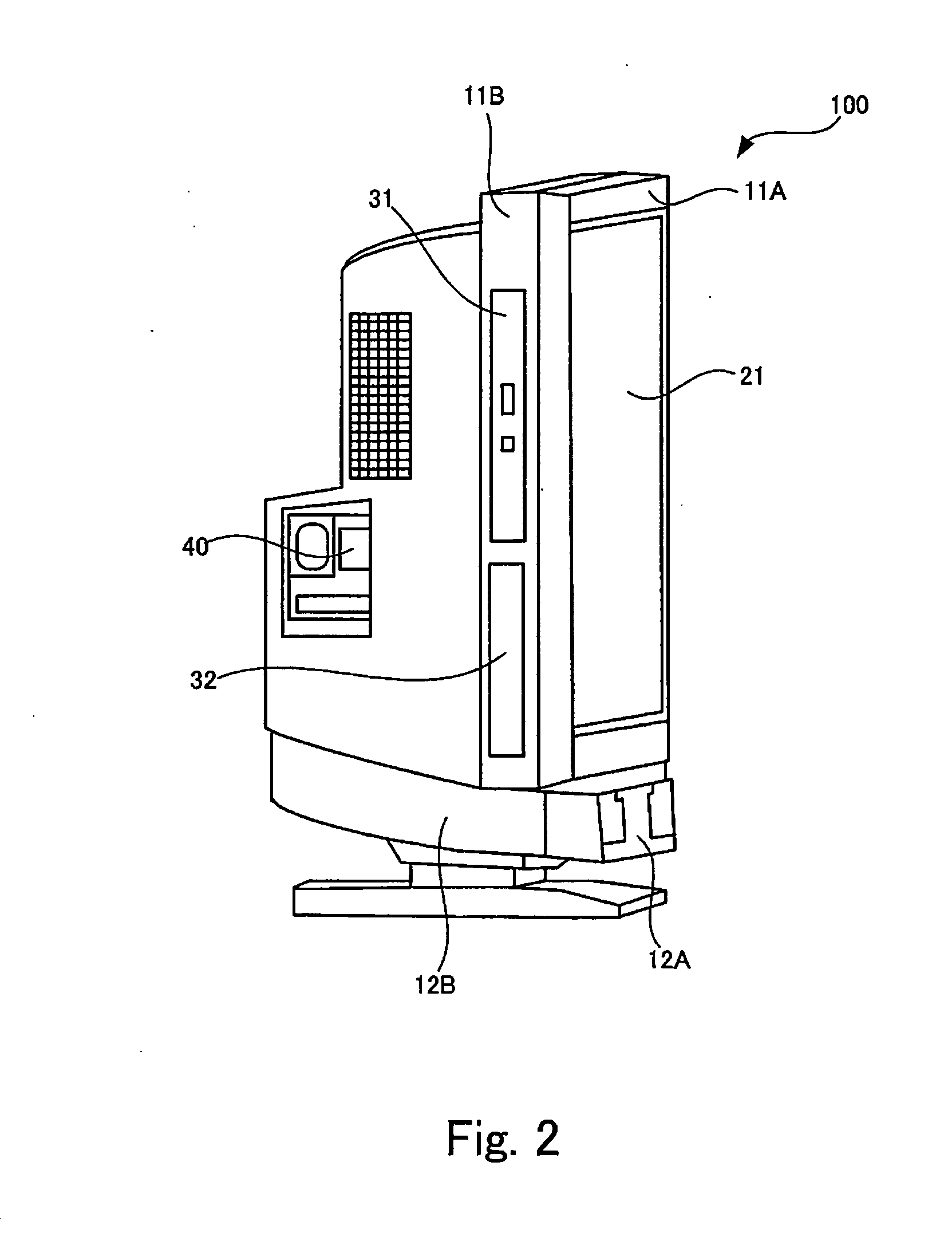
[0042]FIG. 1 is an exterior view of a personal computer 100 of an electronic device.

[0043]The personal computer 100 is an integrated-type personal computer in which a display device for displaying information, a hard disk drive, and the CPU are all built into a same casing. Note that although the personal computer 100 is, in reality, connected to a mouse and a keyboard, these are omitted in FIG. 1.

[0044]FIG. 1 shows the personal computer 100 as viewed from the front. In a space defined by a upper front casing 11A, an upper rear casing 11B, a lower front casing 12A, and a lower rear casing 12B, the personal computer 100 contains a liquid crystal panel with a display screen 21 spreading on a surface thereof, a CPU, a hard disk drive, a cooling fan, a power supply device, various circuit boards, cables for connecting them to each other, and other parts. A combination of the upper front casing 11A, the upper rear casing 11B, the lower front casing 12A and the lower rear casing 12B corre...

second embodiment

[0071]FIG. 12 is an enlarged view of a rear surface side of a printed circuit board 310 used in a personal computer which is the specific second embodiment of the electronic device.

[0072]The printed circuit board 310 of the present embodiment differs from the printed circuit board 260 of the first embodiment shown in FIG. 9 in that a recess 311 rather than the through hole 261 is provided in a periphery of the connector 262. The recess 311 corresponds to an example of the “recess formed in an edge section of the circuit board” in the basic aspects described above.

[0073]Similar to the through hole 261 shown in FIG. 9, the recess 311 is several millimeters longer than a longitudinal direction length of the connector 262 and is formed in parallel with the connector 262.

[0074]Since the recess 311 formed in this way in the printed circuit board 310 in place of the through hole also restrains movement of the cable, it is possible to prevent the cable from being damaged and being pulled ou...

third embodiment

[0076]FIG. 13 is an enlarged view of a rear surface side of a printed circuit board 320 used in a personal computer which is the specific third embodiment of the electronic device.

[0077]The printed circuit board 320 of the present embodiment is proved with a cut-out section 311 different from the recess 311 provided in the printed circuit board 310 of the second embodiment shown in FIG. 12 The cut-out section 311 is corresponds to an example of the “recess formed in an edge section of the circuit board” in the basic aspects described above.

[0078]In the printed circuit board 320 shown in FIG. 13, an edge on the side where the cut-out section 311 is provided is in contact with the frame 240 and a through hole is formed by the printed circuit board 320 and the frame 240. By providing the cut-out section 311 in the printed circuit board 320 and having another member make contact with an edge of the printed circuit board 320 in this way, the opening section 312 of the recess 311 shown in...


PUM


Abstract

The invention provides a printed circuit board including a first surface, a second surface which is a rear surface to the first surface, a connector installed on the first surface, and, formed between the first surface and the second surface, one of a through hole piercing the printed circuit board and a recess formed in an edge section of the printed circuit board; a cable including a first terminal that is removably fitted to the connector and a connecting wire portion located between the first terminal and a second terminal, the connecting wire portion extending from the first surface to the second surface of the printed circuit board through the one of the through hole and the recess when the first terminal is in a state of being fitted to the connector; and a casing for containing the printed circuit board and the cable.

Description

BACKGROUND OF THE INVENTION[0001]1. Field of the Invention[0002]The present invention relates to an electronic device and a printed circuit board unit including a printed circuit board and a cable to be attached to a connector of the printed circuit board.[0003]2. Description of the Related Art[0004]In the field of personal computer, it is required to fulfill both requirements of miniaturization and weigh reduction of a device and upsizing of a display screen. To fulfill these requirements, a variety of techniques have been used as a display device using a thin and light liquid crystal panel is applied, a light source, a control board and the like are arranged behind a liquid crystal panel rather than in a side thereof, so that a display screen is widened according to a narrowed gap between a casing and the liquid crystal panel. Further, an integrated-type desktop personal computer in which a CPU, a hard disk and a display device are housed within a same casing has appeared. Thus, m...

Claims


Application Information

Patent Timeline
Patent Type & Authority Applications(United States)
IPC IPC(8): H01R13/58H01R12/71
CPCH01R13/5833H01R23/661H05K1/147H05K2201/10356H05K2201/09063H05K2201/10189H05K2201/048H01R12/772G06F1/16G06F1/183G06F3/14H01R12/00G06F2212/3035G06F2113/16
Inventor FUJIKAWA, HIDEYUKIHAGIMOTO, HIROMITSU
Owner FUJITSU LTD
Why Eureka
Try Eureka